
Dynamical analysis of high-pressure supercritical carbon dioxide jet in well drilling*
2013-06-01 12:29DUYukun杜玉昆WANGRuihe王瑞和NIHongjian倪紅堅
水動力學研究與進展 B輯 2013年4期
DU Yu-kun (杜玉昆), WANG Rui-he (王瑞和), NI Hong-jian (倪紅堅)
College of Petroleum Engineering, China University of Petroleum (East China), Qingdao 266580, China, E-mail: duyukun_100@hotmail.com
HUANG Zhi-yuan (黃志遠)
Drilling Technology Research Institute, Sinopec Shengli Oilfield, Dongying 257000, China
LI Mu-kun (李木坤)
College of Petroleum Engineering, China University of Petroleum (East China), Qingdao 266580, China
Dynamical analysis of high-pressure supercritical carbon dioxide jet in well drilling*
DU Yu-kun (杜玉昆), WANG Rui-he (王瑞和), NI Hong-jian (倪紅堅)
College of Petroleum Engineering, China University of Petroleum (East China), Qingdao 266580, China, E-mail: duyukun_100@hotmail.com
HUANG Zhi-yuan (黃志遠)
Drilling Technology Research Institute, Sinopec Shengli Oilfield, Dongying 257000, China
LI Mu-kun (李木坤)
College of Petroleum Engineering, China University of Petroleum (East China), Qingdao 266580, China
(Received June 11, 2012, Revised December 10, 2012)
This paper presents the design of an experimental setup and mathematical and physical models to determine the dynamical characteristics of the high-pressure supercritical carbon dioxide (SC-CO2) jet with a highly potential applications in the well drilling. The effects of three major factors on the wellbore dynamical characteristics of the high-pressure SC-CO2jet, i.e., the nozzle diameter, the standoff distance and the jet pressure are determined. It is indicated that the pressure of CO2reduces severely in the SC-CO2jet impact process. It is also found that the bottom-hole pressure and the temperature increase as the nozzle diameter increases but decrease with the increase of the standoff distance. The higher the jet pressure at the wellbore inlet is, the higher the pressure and the lower the temperature at the bottom-hole will be.
supercritical carbon dioxide, wellbore dynamics, experimental determination
Introduction
Unconventional oil and gas resources such as the low-permeability oil and gas, the heavy oil, the tight gas, the shale gas and the coalbed methane have become major alternative energy resources due to the increasing energy demand. Thus, new methods were proposed and new technologies were developed to effectively exploit these unconventional oil and gas resources[1-3].
SC-CO2is an ideal alternative to replace water, and it was demonstrated by Kolle that SC-CO2can penetrate the formation rock and improve the rate of the penetration at a lower pressure[3]. In addition, Kolle and Gupta et al.[4-8]suggested that the advantageous properties of SC-CO2,including the low viscosity, the high density, and the large diffusivity, make it possible to improve the hole-cleaning performance and to reduce the formation damage.
Previous studies were mainly focused on the density, the viscosity, the heat capacity, the heat transfer, the extraction, the enhanced oil recovery and the sequestration storage of CO2[9-14]. The pure CO2is a highly potential drilling fluid, however, rather few experimental data were available in literature with regard to the wellbore dynamical characteristics of SCCO2jet due to the complexity of the jet process[15,16]. In this study, an experimental setup is designed and the mathematical and physical models are established to determine the wellbore dynamical characteristics of high-pressure SC-CO2jet with consideration of various influencing factors.
1. Materials and methods
1.1 Exper imental flow-p roc ess
Theflow-processoftheSC-CO2drillingandcompletion experimental system is shown in Fig.1[17]. The experimental setup includes the storage tank, the boost pumps, the heater, the experimental wellbore, the solid separator, the liquid separator and the refrigerator. The booster pumps can be used to pressurize the pure CO2up to 100 MPa. The pressurized SC-CO2flows into the experimental wellbore after being heated to the temperature above the critical point of CO2using the heater, and then flows out of the wellbore after reacting with the rock core. Then the solid cuttings and the water vapor are removed by the solid separator and the liquid separator. Finally, the pure CO2fluid is cooled down using the refrigerator and returns to the storage tank.
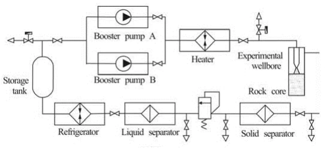
Fig.1 Flowchart of the SC-CO2drilling and completion experimental system
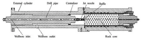
Fig.2 Experimental wellbore
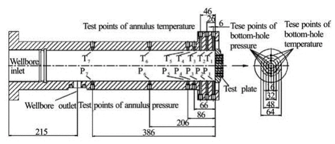
Fig.3 Test point positions in the wellbore
1.2 Experimental wellbore
The experimental wellbore shown in Fig.2 is designed to test the SC-CO2jet’s dynamical characteristics and to effectively simulate the actual drilling process regarding various factors, including the confining pressure and the formation temperature. The back pressure valve between the wellbore and the separator can control the pressure state inside the wellbore, and combined with the relief valve near the outlet of wellbore it can rapidly release the wellbore pressure in the case of overpressure. Three jet nozzles with diameter ()D of 0.0016 m, 0.0023 m and 0.0046 m are used in the experiments while the standoff distance ()H can be adjusted from 0.002 m to 0.05 m. The pressure and the temperature of the SC-CO2in the experimental wellbore can be recorded by the data acquisition system. Test results show that the circulating cuttings can be effectively transported by the SC-CO2drilling fluid.
The pressure and the temperature of the SC-CO2at the surface of the bottom-hole rock core can be tested by using the test plate to replace the rock core in Fig.2. The test points at the bottom-hole surface and the wellbore annulus are arranged as shown in Fig.3. There are five pressure test points and four tempera-ture test points on the bottom-hole surface, while seven pressure test points and seven temperature test points are on the wellbore annulus.
1.3 Experimental procedure
The experiment will follow the following procedure:
(1) Switch on the heater and the refrigerator to the required temperatures.
(2) Charge sufficient liquid CO2into the CO2storage tank.
(3) Put a test plate into the experimental wellbore as shown in Fig.2.
(4) Turn on the booster pumps and adjust the rotation speed to pressurize the SC-CO2to the required jet pressure at the wellbore inlet.
(5) Turn off the booster pumps after the required jet time.
2. Numerical model
2.1 Mathematical formulation
The standard kε- two equation turbulence model under high Reynolds number is chosen for establishing the mathematical model in this paper. The basic equations can be expressed as follows:
Continuity equation
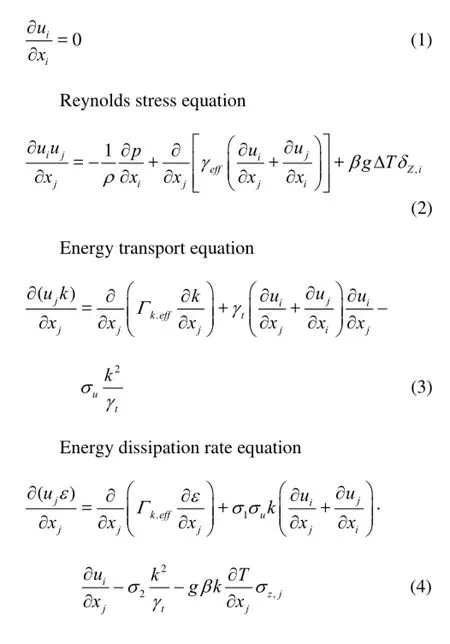
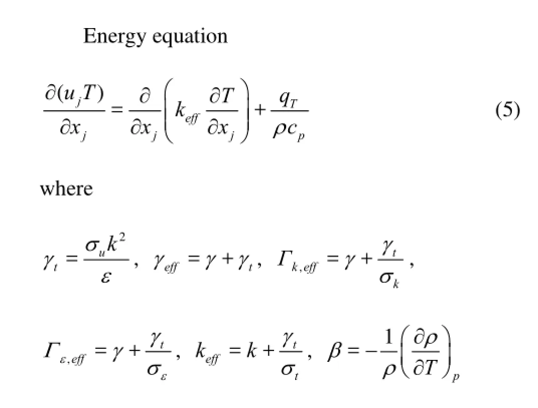
uiis the speed in the coordinate direction i, ujis the speed in the coordinate direction j, xiand xjare the distances from the entry point, p is the pressure, k is the turbulent kinetic energy, ε is the dissipation rate of turbulent kinetic energy, σ is the turbulent Prandtl number, Cpis the fluid heat capacity, qTis the heat of fluid, T is the fluid temperature.
2.2 Physical model
The physical model is designed as shown in Fig.4 according to the experimental setup. The pump flow rate is 32 L/s, the nozzle diameter ranges from 0.001 m to 0.004 m and the standoff distance ranges from 0.003 m to 0.0012 m.
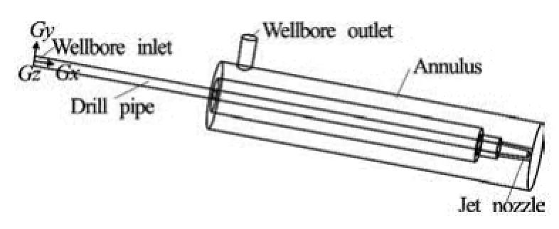
Fig.4 Physical model
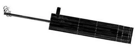
Fig.5 Schematic diagram of whole grid meshing
Due to the fact that the phase change of the carbon dioxide fluid in the jet process is severe, the flow field grid near the nozzle is locally refined, and the tetrahedron and parallelepiped grids are used to generate the mesh of the flow field comprehensively considering the accuracy and the speed of the calculation as shown in Fig.5, There are 565 773 nodes and 584 455 mixed cells in the model.2.3 Boundary conditions
Inlet boundary: The inlet pressure is chosen as the wellbore inlet boundary condition because it can be controlled by adjusting the rotation speed of the booster pumps.
Outlet boundary: The pressure and the velocity at the wellbore outlet are unpredictable for the phase state changes with the changing pressure at the wellbore inlet. While the mass flow at the wellbore outlet can be calculated at a certain rotation speed of the booster pumps so that the mass outlet is chosen as the wellbore outlet boundary condition.
Solid surface boundary: The no-slip boundary method with the wall-function is employed to analyze the solid surface boundary in this study.
3. Analysis results
3.1 Distribution of flow characteristics in wellbore
The pressure distribution of CO2in the wellbore is shown in Fig.6 under the following conditions: the jet pressure at the wellbore inlet is 30 MPa, the temperature is 70oC, the nozzle diameter is 0.0023 m and the standoff distance is twice of the nozzle diameter, that is, 0.0046 m. It can be seen that the pressure of CO2changes little in the drill pipe while it decreases greatly in the bottom-hole jet impact process and continues to decrease during the flow along the annulus and out of wellbore outlet.
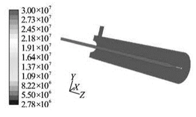
Fig.6 Distribution of wellbore pressure in the jet process
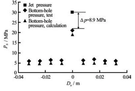
Fig.7 Distribution of bottom-hole pressure
The pressure distribution curves of CO2in the bottom-hole (pb) with different distance to bottomhole jet center point (Db) and in annulus (pa) with different distance to bottom-hole surface (Da) are shown in Fig.7 and Fig.8, respectively. It can be seen that the numerical calculation tallies well with the test results. The bottom-hole pressure drop as compared with the jet pressure at the wellbore inlet reaches 8.9 MPa in the jet impact process, the bottom-hole pressure decreases from the center point to the surrounding area, and the pressure in the annulus reduces until CO2flows out of the wellbore.
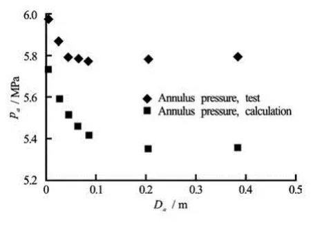
Fig.8 Distribution of annulus pressure
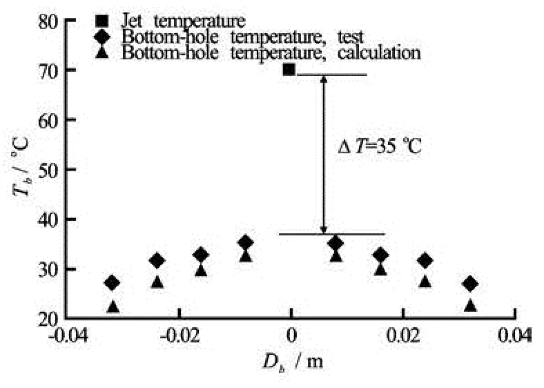
Fig.9 Distribution of bottom-hole temperature
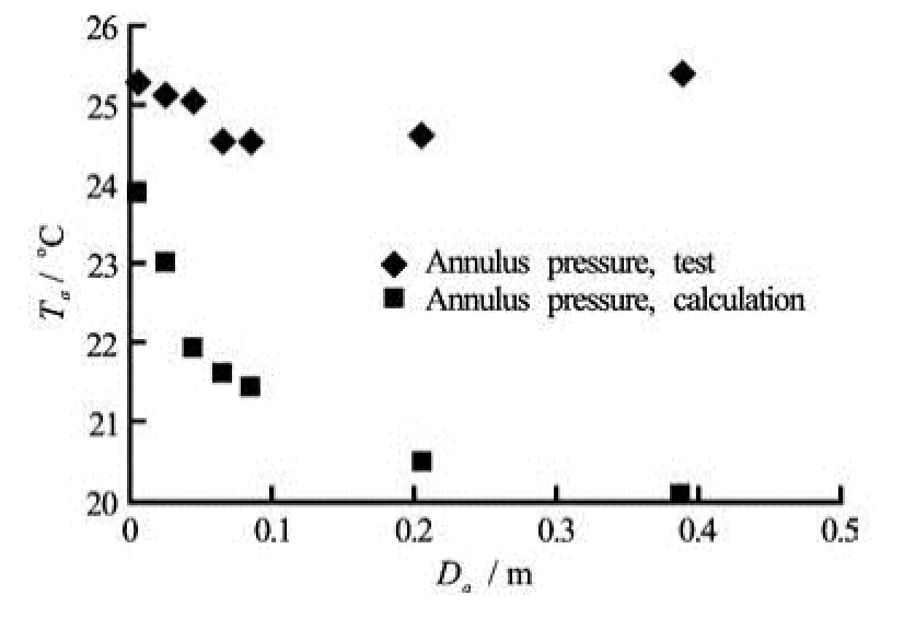
Fig.10 Distribution of annulus temperature
The temperature distribution curves of CO2in the bottom-hole (Tb) and the annulus (Ta) are shown in Fig.9 and Fig.10, respectively. The bottom-hole temperature drop as compared with the jet temperature atthe wellbore inlet reaches 35oC in the jet impact process and the bottom-hole temperature decreases gradually from the jet impact center to the surrounding area. But the test temperature in the annulus rises while the calculation temperature reduces gradually near the wellbore outlet. This is because the wellbore in the lab is much shorter than the real drilling wellbore and it makes the heat easer to transfer from the wellbore inlet to the outlet so that the temperature drop of the fluid itself in the annulus is covered up.
Fig.11 Effect of nozzle diameter on bottom-hole pressure
Fig.12 Effect of nozzle diameter on bottom-hole temperature
3.2 Dynamical characteristics of bottom-hole jet
3.2.1 Effect of nozzle diameter
Experiments are conducted to examine the effect of the nozzle diameter ()D on the bottom-hole jet dynamical characteristics as shown in Fig.11 and Fig.12 under the following conditions: the jet pressure and temperature at wellbore inlet is 30 MPa and 70oC, respectively. The standoff distance is 0.0046 m. It can be seen that the bottom-hole pressure increases while the pressure drop as compared with the jet pressure decreases with the increase of the nozzle diameter. The corresponding bottom-hole temperature shows that the smaller the nozzle diameter is, the lower the temperature and greater the temperature drop will be in the jet impact process. The phase state of CO2changes dramatically when the bottom-hole temperature is low enough, e.g., the state goes from the supercritical phase into the gaseous phase when the temperature drop reaches 40oC at the bottom-hole with 0.0016 m diameter nozzle.
Fig.13 Effect of standoff distance on bottom-hole pressure
Fig.14 Effect of standoff distance on bottom-hole temperature
3.2.2 Effect of standoff distance
Experiments are carried out to examine the effect of the standoff distance ()H on the bottom-hole jet dynamical characteristics, as shown in Fig.13 and Fig.14 under the following conditions: the jet pressure and temperature at wellbore inlet is 30 MPa and 70oC, respectively and the nozzle diameter is 0.0023 m. It can be seen that the bottom-hole pressure decreases with the increase of the standoff distance. The corresponding bottom-hole temperature shows that the larger the standoff distance is, the lower the temperature will be in the jet impact process. The initial high pressure and temperature with a small standoff distance can be attributed to two factors. First, the SC-CO2jet has not been fully developed when the standoff distance is too small. Second, the mutual interaction between the incoming jet and the returning flow is strong with a small standoff distance. Then the further increase of the standoff distance leads to a significant reduction of the jet axial velocity, which results in a decreased pressure and temperature.
3.2.3 Effect of jet pressure
The variations of the bottom-hole pressure and the temperature with the jet pressure ()p at the wellbore inlet are shown in Fig.15 and Fig.16 under the following conditions: the jet temperature at the wellbore inlet is 70oC, the nozzle diameter is 0.0023 mand the standoff distance is 0.0046 m. It can be seen that the numerical calculation tallies well with the test results. It is shown that the higher the pressure is at the wellbore inlet, the higher the pressure and lower the temperature will be at the bottom hole. But the greater the pressure and temperature drop will take place in the jet process. The pressure drop increases from 7.1 MPa to 13.5 MPa when the pressure at the wellbore inlet increases from 25 MPa to 45 MPa. The reason is that the jet speeds up and the fluid phase state change is much greater when the pressure at the wellbore inlet becomes larger.
Fig.15 Effect of jet pressure on bottom-hole pressure
Fig.16 Effect of jet pressure on bottom-hole temperature
4. Conclusions
(1) An experimental setup is designed and mathematical and physical models are established in this study to determine the dynamical characteristics of high-pressure SC-CO2jet at the bottom-hole and wellbore annulus.
(2) The pressure of CO2changes little in the drill pipe while it decreases greatly in the bottom-hole jet impact process and continues to reduce during the flow along the annulus and out of the wellbore outlet.
(3) The wellbore pressure and temperature increase while the pressure drop decreases with the increase of the nozzle diameter. The phase state of CO2turns from the supercritical phase into the gaseous phase when the temperature drop reaches 40oC at the bottom-hole with 0.0016 m diameter nozzle. The bottom-hole pressure and temperature decrease with the increase of the standoff distance. The higher the jet pressure at the wellbore inlet is, the higher the pressure and lower the temperature at the bottom-hole will be and the greater the pressure drop will be in the jetting process.
The promising experimental findings in this study demonstrate that it is important to control the phase state of CO2in the potential applications in the drilling field.
Acknowledgement
This work was supported by the Excellent Ph. D. Thesis Training Fund of China University of Petroleum, the Fundamental Research Funds for the Central Universities (Grant No. 11CX06021A).
[1] WINTER E M. Availability of depleted oi1and gas reservoirs for disposal of carbon dioxide in the United States[J]. Energy Conversion and Management, 2001, 34(6): 1177-1187.
[2] ZHAO Ming-guo, ZHOU Hai-fei and CHEN Ding-feng. Investigation and application on gas-driving development in ultra-low permeability reservoirs[J]. Journal of Hydrodynamics, 2008, 20(2): 254-260.
[3] WANG Ke-liang, LIANG Shou-cheng and YUAN Xinqiang et al. Seepage ability of high-pressure hot composite foam in porous media[J]. Journal of Hydrodynamics, 2010, 22(1): 91-95.
[4] KOLLE J. J. Coiled-tubing drilling with supercritical carbon dioxide[C]. SPE/CIM International Conference on Horizontal Well Technology. Calgary, Alberta, Canada, 2000, 1-9.
[5] GUPTA A. P., GUPTA A. and LANGLINAIS J. Feasibility of supercritical carbon dioxide as a drilling fluid for deep underbalanced drilling operation[C]. SPE Annual Technical Conference and Exhibition. Dallas, Texas, USA, 2005, 1-10.
[6] FAISAL A. Mechanistic modeling of an underbalanced drilling operation utilizing supercritical carbon dioxide[D]. Baton Rouge, Louisiana, USA: Louisiana State University, 2007.
[7] ZEKRI A. Y., ALMEHAIDEB R. A. and SHEDID S. A. Displavement efficiency of supercritical CO2flooding in tight carbonate rocks under immiscible and miscible conditions[C]. SPE Europec/EAGE Annual Conference and Exhibition. Vienna, Austria, 2006, 1-7.
[8] SHEN Ping-ping, JIANG Huai-you and CHEN Yongwu. EOR study of CO2injection[J]. Special Oil and Gas Reservoirs, 2007, 14(3): 1-4(in Chinese).
[9] CARROLL J. J., BOYLE T. B. Calculation of acid gas density in the vapor, liquid and dense phase region[C]. 51st Canadian Chemical Engineering Conference. Calgary, Alberta, Canada, 2001, 1-7.
[10] SMITH J. M., VANN NESS H. C. and ABBOTT M. Introduction to chemical engineering thermodynamics[M]. 7th Edition, New York: McGraw Hill, 2004.
[11] POLING B. E., PRAUSNITZ J. M. and O’CONNELL J. P. Properties of gases and liquids[M]. 5th Edition, New York, USA: McGraw Hill, 2001.
[12] QI Xin-hua, ZHUANG Yuan-yi. Appliance of supercritical fluid technology in the field of environment science[M]. Beijing, China: Science Press, 2005(in Chinese).
[13] YANG D., GU Y. and TONTIWACHWUTHIKUL P. Wettability determination of the crude oil-reservoir brine-reservoir rock systems with dissolution of CO2at high pressures and elevated temperatures[J]. Energy and Fuels, 2008, 22(4): 2362-2371.
[14] YANG F., BAI B. and DUNN-NORMAN S. Modeling the effects of completion techniques and formation heterogeneity on CO2sequestration in shallow and deep saline aquifers[J]. Environmental Earth Sciences, 2011, 64(3): 841-849.
[15] WANG Rui-he, DU Yu-kun and NI Hong-jian et al. Hydrodynamic analysis of suck-in pulsed jet in well drilling[J]. Journal of Hydrodynamics, 2011, 23(1): 34-41.
[16] NI Hong-jian, WANG Rui-he and GE H. K. Numerical simulation on rock breaking under high pressure water jet[J]. Chinese Journal of Rock Mechanics and Engineering, 2004, 23(4): 550-554(in Chinese).
[17] WANG Rui-he, NI Hong-jian and DU Yu-kun. Supercritical fluid drilling and completion simulation experiment device[P]. CN Patent, 201120017722.X, 2011-08-10(in Chinese).
10.1016/S1001-6058(11)60392-3
* Project supported by the National Natural Science Foundation of China (50974130, 51034007), the National Basic Research Development Program of China (973 Program, Grant No. 2010CB226700).
Biography: DU Yu-kun (1983-), Male, Ph. D., Lecturer
猜你喜歡
Chinese Physics B(2022年11期)2022-11-21
Chinese Physics B(2022年8期)2022-08-31
Chinese Physics B(2022年4期)2022-04-12
作文評點報·低幼版(2020年42期)2020-12-14
Chinese Physics B(2019年6期)2019-06-18
小小說月刊·下半月(2017年10期)2017-10-27
婚育與健康(2017年7期)2017-09-11
故事林(2017年9期)2017-05-20
小學生作文·小學低年級適用(2016年1期)2016-03-07
學周刊(2015年1期)2015-07-09

- 水動力學研究與進展 B輯的其它文章
- Ship bow waves*
- Progress in numerical simulation of cavitating water jets*
- Three-dimensional large eddy simulation and vorticity analysis of unsteady cavitating flow around a twisted hydrofoil*
- Numerical simulation of shallow-water flooding using a two-dimensional finite volume model*
- Micropaticle transport and deposition from electrokinetic microflow in a 90obend*
- Simulation and analysis of ice processes in an artificial open channel*