
Wave-current i*mpacts on surface-piercing structure based on a fully nonlinear numerical tank
2015-02-16 06:43LIYong李勇LINMian林緬
水動力學研究與進展 B輯 2015年1期
關鍵詞:李勇
LI Yong (李勇), LIN Mian (林緬)
Institute of Mechanics, Chinese Academy of Sciences, Beijing 100190, China, E-mail: liyong@imech.ac.cn
Wave-current i*mpacts on surface-piercing structure based on a fully nonlinear numerical tank
LI Yong (李勇), LIN Mian (林緬)
Institute of Mechanics, Chinese Academy of Sciences, Beijing 100190, China, E-mail: liyong@imech.ac.cn
(Received September 5, 2014, Revised October 24, 2014)
Fully nonlinear wave-body interactions for a surface-piercing structure with combined wave-current flow in different water depths are studied by using a 2-D numerical tank. The model is based on Reynolds averaged Navier-Stokes (RANS) equations and renormalization group (RNG) -kε model. The mean and maximum wave-current impacts, including forces in two directions and rotational moment, are calculated and discussed. The effects of /U C and water depth condition on forces and moment have been investigated and the results for combined irregular waves and currents are compared with those induced by combined regular waves and currents.
numerical wave-current tank, wave-current impacts, surface-piercing structure, irregular wave, wave spectrum
Introduction
Waves and currents coexist simultaneously in many coastal regions. The combined wave-current flow plays a very important role in wave impacts on coastal structures. In general, the coexistence of current can significantly alter the magnitude and frequency of wave loadings. Recently, many different types of surface-piercing structures, such as floating breakwater (as showed in Fig.1), jacket platform and manmade island, have been widely used in coastal and offshore regions. So it is necessary to be able to predict accurately the wave loads on surface-piercing structures in wave-current flows for the design of the structure and the associated environment impacts to the surroundings.
Wave-current interaction has been analyzed by experimental, analytical and numerical methods[1,2].

Fig.1 Surface-piercing structure in ocean (floating breakwater)
The interactions between the water wave/current and structure had been studied by many authors. Various types of structures were considered, such as the fully submerged bodies[3,4], vertical cylinders/walls[5,6]and the surface-piercing structures[7-11]. Among these studies, the interactions between water waves and surface-piercing bodies have attracted many attentions in recent years. Koo and Kim[9,10]studied the wave body interactions for stationary surface-piercing single and double bodies by a 2-D fully nonlinear numerical wave tank. The wave tank is developed based on the potential theory and boundary element method (BEM) with constant panels. Li and Lin[11]investigated the fully nonlinear wave-body interactions for a surfacepiercing body in finite water depth with flat/slop bottom topography. A 2-D numerical regular wave tankwas built based on the spatially averaged Navier-Stokes equations and the -kε model. In these researches, the regular wave and/or current had been considered under the condition of deep water depth. However, the irregular waves behavior differently in many aspects in comparison with the regular waves. It is vitally important to understand nonlinear interactions between wave-current flow and surface-piercing structure for regular and irregular waves.
The numerical wave tank has been developed to be a promising tool to investigate various ocean-related problems[12,13]. Treatments of wave generation and absorption for numerical wave tank have been investigated by many authors. Fully nonlinear wave-current numerical wave tanks were investigated based on the potential theory and BEM[14,15].
In present work, a numerical wave–current tank is proposed based on RANS equations and RNG twoequation turbulence model. Using the fully nonlinear vertical 2-D numerical tank, the wave forces and rotational moment on a surface-piercing structure are discussed with different /U C (the ratio of current velocity to wave celerity) and the effects of water depth on wave-current impacts are also considered. The numerical tank is verified firstly by comparing the simulated results with the theoretical/experimental data. The flow characteristic of wave-current tank is discussed. Then, mean and maximum wave forces and rotational moment are investigated with different /U C in water of deep and finite depths.
1. Mathematical formulation
1.1 Governing equations
The governing equations are the RANS equations, which can be written as follows:
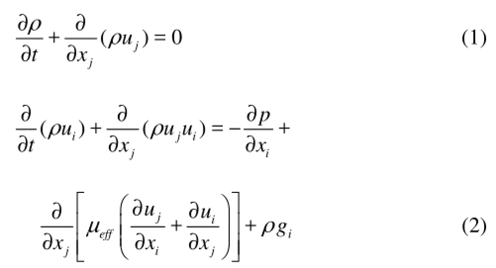
where xj(j=x, y) represents the coordinate component, ju is the fluid velocity, p is the pressure, ρ is the density, g is the acceleration of gravity, μeff= μ+μf, μ is the fluid viscosity, μ=1.002×10⁻⁶m2/s, μfis the turbulent eddy viscosity, μf=Cμρk2/ε. k is the turbulent kinetic energy, and ε is the turbulent energy dissipation rate. Here, the RNG -kε model is adopted to estimate the k and epsilon. The model is generally more suitable and can give better calculation results for a wide range of turbulence phenomena compared with the widely used -kε model.

where

The values of constants in RNG -kε model are set as follows: Cμ=0.0845, αk=αε=1.39, C1ε=1.42, C2ε=1.68, η0=4.38, β=0.012.
For the purpose of capturing the water-air free surface, an Eulerian method named the volume of fluid (VOF) method is adopted. The equation for the volume fraction is

where α is the volume fraction of water and 1αrepresents the volume fraction of air. Volume fraction of each liquid is used as the weighting factor to get the mixture properties, including the density and molecule viscosity, and so on.

Fig.2 Sketch of the fluid domain
1.2 Regular and irregular wave simulation
The entire computational domain is shown in Fig.2. Boundary conditions associated with regular and irregular waves are prescribed along the inlet of computational domain.
The velocity vector of regular wave is specified by Stokes wave theory. In the irregular wave simulation, the modified JONSWAP spectrum is chosen as the target spectrum, which can be expressed as follows:

where S is the spectrum for irregular wave. 1/3H and T1/3are the significant wave height and period, respectively. f is the frequency. γ is the peak enhancement factor, =3.3γ. pT and pf denote the wave period and the frequency at the spectral peak, respectively.
The surface fluctuations and velocities of irregular wave in wave-generating region can be obtained with


1.3 Wave-current simulation
The velocity vector of wave-current flow is specified as follows:


where y?=u*( d+y)/5v , ∏ is the wake intensity, u*is the friction velocity, d is the water depth. The vertical velocity,ycu is set to zero.
In addition, in order to satisfy the stability condition, wave profile and velocity at the inflow boundary was increased gradually from a still water condition towards the targeted values by using a modulation function. The modified profile and velocity at first wave period can be written as

where ()f t is the modulation function, expressed as

1.4 Damping zones for wave-current simulation
For the purpose of absorbing the wave energy reflection from structure wall, end-wall and re-reflection from input boundary, artificial damping zones are located at the two ends of domain.

As for the right damping zone, the horizontal velocityxu in this area is modified by the average velocity of last period, which can be expressed as ux,m=ux+(ux-ux)/D′′. D′′ is also a dissipative coefficient, defined as

where0x is the distance from origin to the starting point of damping zone. n and θ are the damping coefficients, =2n, =0.6θ.
2. Numerical implementation and verification
2.1 Numerical implementation
The equations are discretized based on the finite volume method (FVM). The preconditioning conjugate gradient (PCG) method is employed for solving the algebraic equations. The pressure implicit splitting of operators (PISO) scheme is employed to treat the pressure-velocity coupling. The turbulence equations are coupled in the scheme and solved by a segregated approach. As for the free surface simulation, a compressive interface capturing scheme for arbitrary meshes (CICSAM) is used to capture the fluid interfaces.
The code is programmed based on the open source C++ CFD toolbox named open field operation and manipulation (OpenFOAM). The core technology of OpenFOAM is a flexible set of efficient C++ modules. OpenFOAM is open not only in terms of source code, but also in its structure and hierarchical design, so that researchers can fully extend the codes to satisfy their own demands. Here, a new two–fluid code, called irwcFoam, has been developed based on the framework of OpenFOAM. The version of OpenFOAM used here is 2.2.1, which can be downloaded freely through the internet. In the irwcFoam solver, calculation functions, such as regular/irregular wave generation, wave energy absorption, wave-current simulation, and so on, are all implemented.
2.2 Simulation of regular and irregular waves
The total length of the numerical tank is set to be 9.0L with sponge layers at its two ends, each with a length of 3.0L. The computational case is performed with following inputs: H=0.3m , T=2.6s and d=5.0 m . Figure 3 shows the time series of water level at 4.5L away from the wave generator comparing with an analytical solution based Stokes wave theory. The profiles are plotted against the dimensionless time (/)t T. It can be observed that the numerical results agree well with analytical solutions, which indicate that the two sponger layers can absorb the nonlinear wave effectively.
As for the irregular wave, the fast Fourier transform (FFT) is used to analyze the frequency spectrum. Figure 4 illustrates the free surface series of iregular waves at =4.5xL and comparison of wave spectrum with the target spectrum is presented in Fig.5. It can be seen that the incident wave spectra of two cases are consistent with the target spectra. The results indicated that the present numerical wave tank can be used to generate continuous irregular waves.

Fig.4 Time series of irregular wave profile (x=4.5L)

Fig.5 Comparison of wave spectra for T1/3=2.6s (x=4.5L)
2.3 Simulation of wave-current flow
In this section, the characteristics of flow field in numerical wave-current tank are investigated. Two different experiment cases (WC3 and WC10) reported by Van Rijn are used for evaluation of accuracy for the present numerical results[16]. It should be pointed out that only those tests with waves following to currents are considered in present work and tests with waves opposing and perpendicular to current will be studied in the future. Cases and parameters used in Van Rijn’s experiment are listed in Table 1.

Table1 Parameters in experiment

Fig.3 Times series of nonlinear wave profile
When the calculation becomes stably, the mean water level usually keeps unchanged. The calculated vertical distributions of time-average velocity are compared with experimental data in Fig.6. The velocity profile of a pure current has been depicted in the figure. The simulated results are shown to be in goodagreement with the experimental data. It is can be observed that the numerical wave-current tank can predict the reduction of the velocity in the upper part of the water column and the intensification near the bottom. The same phenomena was also mentioned by some other authors, such as Olabarrieta et al.[1]. It indicates that the two dimensional numerical tank has a good wave-current characteristic.

Fig.6 Comparison of vertical distribution for time-average velocity

Table2 Incident wave inputs
2.4 Simulation of wave impact
In order to validate force simulation, the calculated impact results are compared with the experimental data and analytical solution[7]. Table 2 indicates the input wave properties, where ξ=Bω2/2g . The wave height is chosen as 0.07 m. Water depth is equaled to the wave length and h=0.25 m , B=0.5 m . For the purpose of capturing the wave surface accurately and calculating the wave forces precisely, the meshes around in surface and the body are refined.

Fig.7 Comparison of first-harmonic normalized forces
Figure 7 shows the comparison of the normalized force components and rotational moment, wherexF andyF are the force components in the x and y directions, respectively, and M is the moment about the z axis.xF,yF and M are normalized by ρgLhH /2, ρgLBH /2 and ρgLhBH /2, respectively. The first-harmonic force components and moment are obtained by using the Fourier analysis. The figure shows that the calculated results agree well with the experimental and analytical data.
The pressure distribution below the bottom of the surface-piercing body is very important to the body stability. As the probe location moves toward the right side of the body bottom, the mean pressure decreases. It indicates that the negative pressure on the right side bottom exerts a clockwise rotational moment[9].
3. Numerical results and discussions
3.1 Regular wave and current
This section is focused on the impacts on surface-piercing structure due to the combined regular wave and current. There are several different numerical cases have been performed. Table 3 indicates the input wave properties. /L d is the ratio of wave length to water depth. /U C is chosen as 0, 0.05, 0.1, 0.15, 0.2 and 0.25, where C is the wave propagation velocity.

Table3 Incident wave inputs

Fig.8 Time series of calculated normalized forces for /=L d 0.47

Fig.9 Time series of calculated normalized forces for /=L d 0.19
The simulations are performed for 50T. After several period calculations, the steady-state time series results can be obtained. Partial records of L/ d=0.47 (deep water depth) for U/ C=0 and U/ C=0.15 are shown in Fig.8, in which the normalized forces and moment are plotted. The maximum forces and moment are increased for U/ C=0.15 compared with nocurrent cases. There is a similar trend between surface-piercing structure and submerged body in the upper part of the water column. Venugopal et al.[3]investigated the force coefficients obtained for the horizontally submerged square body in combined regular waves and currents. They found that the horizontal and vertical drag coefficients were significantly larger than those obtained for pure wave cases. Furthermore, the inertia coefficients do not show any distinct difference between pure waves and combined wave-current cases.Partial records of L/ d=0.19 in finite water depth are shown in Fig.9. From those two figures, it can be seen that the water depth condition has an especially important effect on the normalizedyF.

Fig.10 The normalized mean and maximum forces on the structure
Koo and Kim[10]studied the horizontal and vertical wave force components. In present paper, the normalized mean and maximum forces and moment on the surface-piercing structure are obtained, as showed in Fig.10. The average and maximum forces and moment for two water depth conditions basically increase with the increase of /U C. Li and Lin[11]showed that the water depth has a significant influence on the wave loads on surface-piercing body. In Fig.10, the normalized mean and maximum vertical forces of /L d=0.19 are significantly greater than those for deep water depth. The differences can be as large as about 50% in the mean and 30% in the maximum values. In addition, in finite water depth, the maximum horizontal force and moment increase rapidly with /U C. The values can be 100% greater than those due to the pure regular waves for the case of U/ C=0.25. In contrast, water depth condition has relatively little influence on the moment. Average rotational moments in finite depth are slightly bigger than those of L/ d=0.47.

Fig.11 Time series of calculated forces for L/ d=0.47
3.2 Irregular wave and current
In this section, the wave impacts for combined irregular wave and current are investigated. The variations of the forces and moment for combined irregular wave and current in deep and finite water depths are showed in Fig.11 and Fig.12, respectively. In these two figures, the simulation results for U/ C=0.15 are compared with those induced by pure irregular waves. The horizontal force and moment for wave-current flow are significant greater than those for pure waves and the vertical normalized force increases obviously in the negative direction. In general, the wave-current impacts on structure cannot be obtained by a simple addition of the wave action and current action[3,10]. In Fig.8 and Fig.9, it can be seen that the impacts in-crease or decrease regularly as a whole on surface-piercing body under combined regular wave and current. However, under irregular wave and current, the loading variation shows no significant regularity compared with those for pure irregular wave (U/ C=0), as illustrated in Fig.11 and Fig.12.

Fig.12 Time series of calculated forces for L/ d=0.19
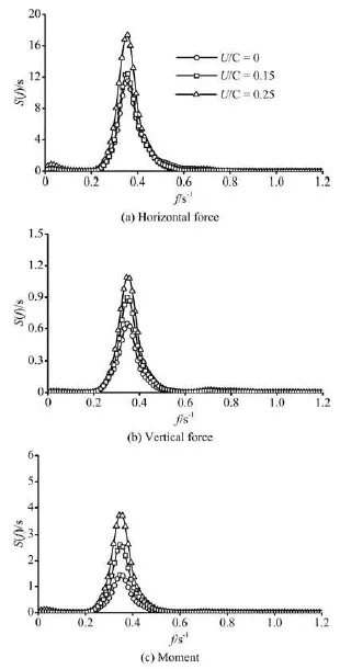
Fig.13 Comparison of amplitude spectra of normalized forces in deep water depth for different /U C
The amplitude spectra of normalized forces and moment for combined irregular wave and current in deep and finite water depths are showed in Fig.13 and Fig.14, respectively. The peak values of amplitude spectra for forces and moment increase with /U C except the spectrum of vertical force in finite water depth. The peaks of spectrum for normalized vertical force decrease with the increase of /U C. Meanwhile, the differences between peaks of spectrum for normalized horizontal forces are bigger compared with those in deep water depth. Furthermore, the peaks of amplitude spectra for rotational moment in cases of /=L d 0.19 are much greater than those in cases of /=L d 0.47 and the magnitude of spectrum peak increases up to 131% of the value at U/ C=0.25. It means that the state of structure become more unstable and dangerous in finite water depth than in deep water, especially when the /U C is high.
Figure 15 shows the maximum normalized forces and moment on the surface-piercing structure. The impacts for all runs basically increase with the increase of /U C. The maximum loadings induced by combined irregular wave and current are obviously greater than those for regular wave and current. The water depth condition plays an important role on the maximumyF. The difference between two water depth conditions increases with /U C and the maximum normalized yF in finite water depth increases up to 139% of value in deep water depth at the case of U/ C=0.25. The normalized mean forces and mome-nt are illustrated in Fig.16. The values for combined regular wave and current are greater than those induced by combined irregular wave and current when U/ C>0.05.

Fig.14 Comparison of amplitude spectra of normalized forces in finite water depth for different /U C
4. Conclusions
In present paper, based on a vertical 2-D fully nonlinear numerical tank, wave-body interactions for a surface-piercing structure with combined wave-currents flow under different /U C and water depths are investigated.
The tank model is based on RANS equations and RNG -kε model. The equations are discretized based on the FVM. The PISO scheme is employed to treat the pressure-velocity coupling and a CICSAM is used to capture the fluid interfaces. A new two-fluid code, called irwcFoam, has been written within the framework of OpenFOAM. The inflow boundary and two damping zones are added into the code and the interface capturing scheme in OpenFOAM for two-phase flow is improved. The simulated results are compared with the theoretical/ experimental data and the numerical results are shown to be in good agreement with analytical/experimental solutions. The mean and maximum wave-current impacts for different /U C and water depths are calculated and the force and moment spectra for combined irregular waves and currents are obtained by FFT.

Fig.15 The maximum normalized forces on the structure
The impacts on surface-piercing body for combined regular waves and currents increase or decrease regularly as a whole, while the loading variations for irregular waves show no significant regularity compared with those for pure irregular cases. The impacts for all runs basically increase with the increase of /U C. The maximum loadings induced by irregular wave-current flows are obviously greater than those by regular wave-current flows, while the average loadings induced by irregular wave-current flows are evi-dently lower than those by regular wave-current flows. In addition, the water depth condition has an important influence on the normalizedyF. The normalized mean and maximum vertical forces in finite water depth are significantly greater than those under deep water depth. The spectrum peaks of normalized vertical force for combined irregular waves and currents decrease with the increase of /U C.
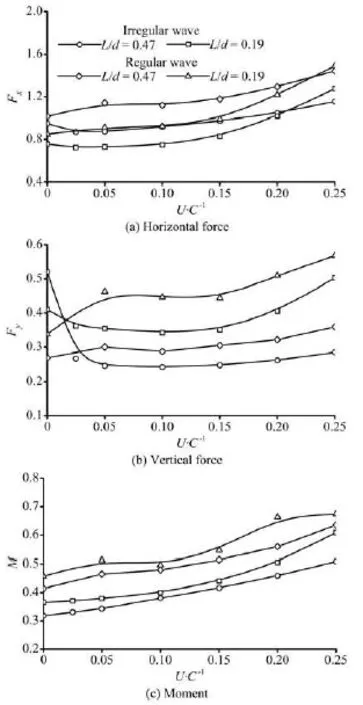
Fig.16 The normalized mean forces on the structure
[1] OLABARRIETA M., MEDINA R. and CASTANEDO S. Effects of wave-current interaction on the current profile[J]. Coastal Engineering, 2010, 57(7): 643-655.
[2] TELES M. J., PIRES SILVA A. A. and BENOIT M. Numerical modeling of wave current interaction at a local scale[J]. Ocean Modelling, 2013, 68(8): 72-87.
[3] VENUGOPAL V., VARYANI K. S. and WESTLAKE P. C. Drag and inertia coefficients for horizontally submerged rectangular cylinders in waves and currents[J]. Journal of Engineering for the Maritime Environment, 2009, 223(1): 121-136.
[4] MARKUS D., ARNOLD M. and WUECHNER R. et al. A virtual free surface (VFS) model for efficient wavecurrent CFD simulation of fully submerged structures[J]. Coastal Engineering, 2014, 89: 85-98.
[5] XIAO H., HUANG W. R. and TAO J. H. Numerical modeling of wave-current forces acting on horizontal cylinder of marine structures by VOF method[J]. Ocean Engineering, 2013, 67: 58-67.
[6] KISACIK D., TROCH P. and Van BOGAERT P. Investigation of uplift impact forces on a vertical wall with an overhanging horizontal cantilever slab[J]. Coastal Engineering, 2014, 90: 12-22.
[7] LI Y., LIN M. Regular and irregular wave impacts on floating body[J]. Ocean Engineering, 2012, 42: 93-101.
[8] FANG M. C., CHEN G. R. The relative motion and wave elevation between two floating structures in waves[C]. Proceedings of the 11th International Offshore and Polar Engineering Conference. Stavanger, Norway, 2001, 361-368.
[9] KOO W. C., KIM M. H. Fully nonlinear wave-body interactions with surface-piercing bodies[J]. Ocean Engineering, 2007, 34(7): 1000-1012.
[10] KOO W. C., KIM M. H. Current effects on nonlinear wave-body interactions by a 2D fully nonlinear numerical wave tank[J]. Journal of Water Way, Port, Coast and Ocean Engineering, 2007, 133(2): 136-146.
[11] LI Yong, LIN Mian. Wave-body interactions for a surface-piercing body in water of finite depth[J]. Journal of Hydrodynamics, 2010, 22(6): 745-752.
[12] CHOI J., YOON S. B. Numerical simulations using momentum source wave-maker applied to RANS equation model[J]. Coastal Engineering, 2009, 56(10): 1043-1060.
[13] GUO Jia-hong, CAO Yang and ZHENG Shu-jun. Numerical research on the mechanism of contaminant release through the porous sediment-overlying water interface[J]. Journal of Hydrodynamics, 2014, 26(6): 971-979.
[14] RYU S., KIM M. H. and LYNETT P. J. Fully nonlinear wave-current interactions and kinematics by a BEM-based numerical wave tank[J]. Computational Mechanics, 2003, 32(4-6): 336-346.
[15] NING De-zhi, CHEN Li-fen and TIAN Hong-guang. A fully nonlinear numerical flume model for wave-current interactions[J]. Journal of Harbin Engineering University, 2010, 31(4): 1-6(in Chinese).
[16] LI Yong, LIN Mian. Three-dimensional wave-current numerical model[J]. Journal of Tsinghua University: Science and Technology, 2010, 50(6): 865-868(in Chinese).
10.1016/S1001-6058(15)60465-6
* Project supported by the National Natural Science Foundation of China (Grant No. 11032007), the Key Instrument Developing Project of the Chinese Academy of Sciences (Grant No. ZDYZ2012-1-08-02).
Biography: LI Yong (1978-), Male, Ph. D., Associate Professor
LIN Mian, E-mail: linmian@imech.ac.cn
猜你喜歡
中國糧食經濟(2020年11期)2020-12-23
齊魯藝苑(2019年5期)2019-11-09
中國衛生(2014年6期)2014-11-10

- 水動力學研究與進展 B輯的其它文章
- 3-D numerical investigation of the wall-bounded co*ncentric annulus flow around a cylindrical body with a special array of cylinders
- Application of support vector machine in drag reduction effect p*rediction of nanoparticles adsorption method on oil reservoir’s micro-channels
- Numerical research on the performances of slot hydrofoil*
- Numeri*cal simulation of 3-D water collapse with an obstacle by FEM-level set method
- Ferrofluid measurements of bottom velocities and shear stresses*
- Flow choking characteristics of slit-type energy dissipaters*