
Effect of perforation on flow past a conic cylinder at Re=100:vortex-shedding pattern and force history
2018-04-18 02:55LinZhongWu
Acta Mechanica Sinica 2018年2期
L.M.Lin·X.F.Zhong·Y.X.Wu
1 Introduction
Bluff bodies are commonly used in many engineering applications,for instance,mooring cables,flexible risers and pipelines between oil platforms and submarine drilling wells,,cables in suspension bridges,and heat exchangers.When flow passes such bodies,vortices are generated due to the fluid viscosity and shed alternately.This phenomenon is critically important,because it gives rise to unsteady loading,further leading to structural vibration known as vortex induced vibration(VIV).When synchronization occurs due to proximity of the vortex shedding frequency to the natural frequency of the structure,the sudden increase of structural oscillation amplitude,as well as fluid forces,may result in structural fatigue failure or destruction of structural integrity.Therefore,a large number of experimental and numerical investigations have been carried out to understand the dynamics of VIV in recent decades.Comprehensive reviews on this subject are given in Refs.[1–4].
Elimination of such vortices alternately shed from bluff bodies is also significant to alleviate the resulting unsteady fluid loading and thereby suppress VIVto improve structural integrity.Many such methods have been proposed over the last half century,mainly aiming to control wake dynamics;For example,control bumps spirally distributed on the surface of a cylinder,as proposed by Owen et al.[5],can reduce the drag by up to 47%,mainly being effective at higher mass-damping parameter.Introduction of triple-starting helical grooves on the surface of a structure has also been found to be effective for suppressing VIV with peak-amplitude reduction of 64%and drag reduction of up to 25%at subcritical Reynolds number[6].By placing two small rotating cylinders in the boundary layer of a large cylinder,drag reduction of up to almost 60%can be achieved[7].Multiple control rods have also been used to suppress VIV of a slender flexible riser[8],leading to reduced displacements in both cross and in-line flows by almost 90%with minimum spacing ratio of 0.187.The ventilated trouser(VT),as an entirely new and innovative quasi-fairing for VIV suppression of cylindrical structures,was proposed and investigated recently by King et al.[9].The VT is a loose- fitting sleeve in the form of alight flexible net with integral bobbins.Recently,a traveling wave wall was proposed as a kind of shape control method to suppress VIV by Xu et al.[10].Generally speaking,streamline fairings exhibit very good aerodynamic performance[11],although this can also be achieved by installing(free-to-rotate)two-dimensional(2-D)splitter plates[12,13],with maximum drag reduction of about60%.To date,use of a helical strake along the riser’s span[14,15]has been the most widely used method to disturb the spanwise uniformity of vortex shedding.More information about these or other passive control methods can be found in various review papers[16–18].
During the last two decades,another method for suppressing VIV has also been proposed,based on introduction of three-dimensional(3-D)geometric disturbances.Such approaches appeared in early research,including a wavy front surface[19]and totally wavy cylinders with invariant circular or square section[20–22]introduced in a streamwise–spanwise plane.The effectiveness of VIV suppression is then sensitive to the specific direction of incoming flow.To achieve omni directionality,introduction of a radial disturbance in a radial–spanwise plane was proposed by Lin et al.[23],including harmonic or conic disturbances.It should be emphasized that these radial disturbances are installed outside of a straight cylinder as a shroud for VIV suppression.Based on experiments and numerical simulations[24–26],such a harmonic disturbance was indeed found to reduce fluid forces within a certain parameter range.Meanwhile,in pendulum VIV experiments[27],the oscillating amplitude was greatly reduced at the start of lock-in by introducing a harmonic or conic-like disturbance,but increased at higher reduced velocity.This indicates that the vortex shedding frequency was also reduced,as verified later based on numerical simulations[28,29].In a basic study,the flow past a fixed circular cylinder with harmonic and conic disturbances atR e=100 was numerically simulated[28,30].The results showed that the behaviors with these two disturbances were qualitatively similar in terms of hydrodynamic parameters,vortex shedding patterns in the near wake,and other flow characteristics for various wavelengths and wave steepness(defined as the ratio of the wave height to wavelength of the wavy disturbance).Subsequently,the flow past a cylinder with a conic disturbance was further investigated at other subcritical Reynolds numbers(103,104,105)[29,31].Generally,as the wave steepness is increased,the drag gradually increases,while the lift first reduces quickly then increases gradually.The vortex shedding frequency gradually decreases with increasing wave steepness.
Based on a conic disturbance,various improvements have been adopted and investigated to further reduce fluid forces as far as possible.In previous work[30],the time-averaged pressure at the peak of a conic disturbance was found to be obviously greater than that at the valley,and the increasing drag was mainly attributed to the greatly increased projected area,which is proportional to the wave steepness.In addition,use of a straight,circular-section,perforated shroud has been proposed as a method for suppressing VIV for over 30 years[16].Thus,perforation of a conic disturbance can be applied using several holes uniformly distributed around the peak,which is referred to as a peak-perforated conic shroud[31,32].Basically,the introduction of such perforation has little effect on the qualitative variations of the hydrodynamic parameters with the wave steepness.However,in a certain range of control parameters,the drag is indeed reduced slightly,while the lift is reduced greatly with maximal reduction of 68%due to the change of the vortex shedding pattern.
Introduction of such VIV suppression methods can interfere with the original wake flow,typically formed of Kármán vortices;For example,control bumps lead to total suppression of vortices in the near wake for a certain wave steepness[5].Introduction of two small rotating cylinders can delay the separation of the boundary layer from the cylinder surface[7].Use of a traveling wave wall results in a series of small-scale vortices formed in the troughs of the traveling wave on the rear of cylinder,effectively controlling the flow separation,and eliminating the oscillating wake[10].The streamlined outer shape of a streamline fairing successfully results in delayed flow separation and thus VIV suppression[11].In the wake of a wholly wavy square-section cylinder[21],the Kármán vortices are totally suppressed in regime III(type A),while large unsteady hairpin structures emerge in the near wake in regime III(type B).For a harmonic disturbed cylinder[26],three different flow patterns were identified,characterized as a wake structure similar to that behind a straight cylinder but with certain spanwise distortions,an enhanced or 3-D wake vortex distortion,and a free shear layer without rolling-up then shedding vortices.Similarly,based on the effect of introduction of radial disturbances on the formation of spanwise vortices,three different flow regimes were also identified for harmonic and conic shrouds[28].Especially in regime III,the Kármán vortices are totally suppressed or disappear,with new kinds of vortices appearing,such as?-type vortices shed at the valley or peak,and “cloud”-like vortices.However,when perforating the peak of a conic shroud,it remains unclear whether other unknown vortex shedding patterns will occur in the near wake,with corresponding related features in the force history.

Fig.1 Schematics of flow past a conic cylinder and b peak-perforated conic shroud with specific angle of attack Ag in c the peak cross-section
In the present study,we aim to qualitatively investigate the vortex shedding pattern and time history of fluid forces for a peak-perforated conic shroud atR e=100 using numerical simulations(FLUENT).Special distributions of the streamwise and vertical components of the vorticity in the near wake and the characteristics of the shear layers are studied.Meanwhile,these vortex patterns are summarized based on the various flow regimes observed in the investigated parameter space.The effects of the angle of attack based on the specific direction of the holes relative to the direction of incoming flow and the diameter of the holes are also investigated.
The remainder of this paper is organized as follows:Numerical simulations(including the physical model,numerical methods,boundary conditions,control parameters,etc.)are presented in Sect.2.Then,in Sect.3,the features of the vortex shedding pattern in different flow regimes with perforations as well as the time history of the drag and lift coefficients(in terms of the angle of attack and the diameter of the holes)are presented in detail.Finally,brief conclusions are made in Sect.4.
2 Numerical simulations
2.1 Physical model
As shown in Fig.1,in compressible flow with constant densityρand kinematic viscosityνpast two kinds of circular-section cylinder was investigated.The first in Fig.1a includes a conic disturbance along the span of a straight circular cylinder,referred to as a conic cylinder or shroud(denoted by “C”),while the other in Fig.1b is obtained by introducing perforations at the peak of the conic disturbance in the form of several circular holes distributed uniformly around th e azimuthal direction,referred to as a peak-perforated conic shroud(denoted by“Co”).The basic conic disturbance can be described mathematically by its wavelengthλ,peak-to-valley wave heightW,and base diameterD.Correspondingly,the peak and valley are defined as the spanwise positions with maximal and minimal diameter,i.e.,(2W+D)andD,respectively.The straight circular cylinder without the conic disturbance can be obtained by reducingWto zero.The perforation is described by the diameterD o,numberN o,and angle of attackAgof the holes.As shown in Fig.1c,Agis defined as the angle between the central axis of the hole near the front stagnation point of the cylinder and the incoming flow.
For the present flow fields,the inertial Cartesian coordinate system(x,y,z)is used.Thex-axis,referred to as the streamwise direction,is aligned with the free upstream flow with uniform velocityU∞.Thez-axis,referred to as the spanwise direction,is aligned with the central axis of the cylinder.Meanwhile,they-axis,referred to as the vertical direction,is perpendicular to the(x,z)plane.The nondimensional continuity and Navier–Stokes equations governing the present flows are then obtained as

whereu=(u,v,w)is the velocity vector,pis the static pressure,tis nondimensional time,? is the gradient operator,andRe=U∞D/νis the Reynolds number.Lengths are scaled by the base diameterDand velocities by the free stream velocityU∞.
In a temporally periodic flow,the frequency of vortex shedding,f,is nondimensionalized as the Strouhal numberSt=f D/U∞.
The fluid forces,i.e.,drag and lift,are normalized by the free-stream dynamic pressure and the projected area of the bodyA,i.e.,12ρU∞2A,to produce the drag and lift coefficients,CDandCL.For comparison of these fluid forces between the straight cylinder and the conic shroud or perforated conic shroud,the projected areaAmust be computed from a straight cylinder with the same spanwise length,i.e.,A=λD,instead of the conic cylinder or perforated conic shroud itself.CD_MandCL_RMSare the mean drag coefficient and root-mean-square(RMS)lift coefficient.

Fig.2 Nondimensional computational domain and typical grid distributions at a z=0 and b z=λ/(2 D),and mesh for holes(circle)near c front and d rear surfaces
2.2 Boundary conditions
To obtain appropriate numerical solutions,proper boundary conditions should be proposed.To simulate the flow around cylinders with infinite spanwise length,it is commonly assumed that the flow is periodical along the spanwise direction.Then,for the boundary conditions in the(x,y)plane,the uniform free-stream velocity(u=(U∞,0,0))at the inlet,simple nonreflecting outflow(?u/?x=0)at the outlet,free slip(?(u,w)/?y=v=0)at the vertical sides,and nonslip boundary condition(u=0)on the surface of the cylinder are prescribed.The reference pressure is zero at the inlet withy=0.
2.3 Computational domain and grid
It is also very important that the computational domain be carefully selected to weaken its effect on the flow field,fluid forces,and vortex shedding frequency as much as possible.Based on previous work by Lin[33],the nondimensional computational domain in the(x,y)plane was considered to be 40×20(x×y)due to present computational resources and costs in time,as shown in Fig.2.The dimensionless computational length along thez-axis is given as one period of the conic disturbance,i.e.,λ/D,regardless of the effect of the large-scale spanwise disturbance(which will be studied in the future).

The measured maximum values.for skewed elements are 0.8–0.85 The number of highly skewed elements does not usually exceed 10–30.Most of these are distributed upstream,near the boundary between the structured and unstructured grids,so they have little effect on the flow near the cylinder or in the near wake.

Table 1 Parameters used in numerical simulations at Re=100
2.4 Numerical methods
Numerical simulations of the flow evolution were carried out using the commercial fluid computation software FLUENT.Due to the laminar flow atRe=100,a laminar viscous model was applied.
Second-order time discretization was applied with nondimensional time step of 0.01,based on a stability estimation for the local velocity and the grid scale using an implicit solver formulation for the pressure-based Navier–Stokes solution algorithm.To control the discretization of the convection terms in the solution equations,a second-order scheme for pressure and second-order upwind scheme for momentum were selected.
In the software,the Green–Gauss node-based method was adopted for computing the gradient of scalars at cell centers.
To compute the pressure–velocity coupling equations,the SIMPLEC algorithm was adopted with zero skewness correction(default value).
After applying the multiple-grid method,a flexible cycle type was chosen with the aggregative algebraic multigrid(AMG)solver for stabilization of all equations.
The maximal convergence residual reached a lowest order ofO(10?4)for the continuity equation,andO(10?5)for the three components of the momentum equations.
2.5 Control parameters
In addition to the Reynolds number,a typical control parameter for the present flow,various other parameters were used,mainly describing the conic disturbance for the conic cylinders and the circular holes for the perforated conic shroud.Firstly,for the conic disturbance,two independent length parameters,viz.the nondimensional wavelengthλ/Dand wave steepnessW/λ,were used to describe the similarity between different conic cylinders.Then,for the perforation,the nondimensional diameter of the holesDo/D,the number of holesN o,and the angle of attackAgwere also used as main control parameters.Therefore,in the present simulated flow,there are six control parameters for the peak-perforated conic shroud,constituting a large parameter space.
In this study,a series of computational investigations were carried out.Based on previous work[29],at various subcritical Reynolds numbers,increasing the Reynolds number has only a slight effect on the qualitative variation of the mean drag,RMS lift,and Strouhal number in flows past a conic cylinder.For this fundamental research,the Reynolds number was therefore set to be100 to keep the flow laminar and avoid introduction of computational effects resulting from use of different turbulence models at higher Reynolds number.As summarized in Table 1,different values of dimensionless wavelengthλ/D,wave steepnessW/λ,nondimensional hole diameterDo/D,angle of attackA g,and number of holesN owere used.Here,only the case with four holes,i.e.,N o=4,is studied(the effect of increasing the number of holes will be investigated in future work).Since the symmetry of the perforation with four holes is around they-axis,the relationship for the angle of attack isAg?360°/(2N o)=45°.
Note that only selected combinations ofDoandAgwere considered due to limited computational resources;For instance,when varyingD o/D,onlyA g=0°was taken into account,and when increasingAg,only cases withDo/D=0.1 were investigated.
2.6 Verification of numerical simulations
Verification IA 2-D simulation was performed for the flow past a circular-section cylinder atRe=100.As shown in Fig.3a,the wake consisted of strong spanwise vortices shedding alternately from the top and bottom shear layers,representing the well-known Kármán vortex street.The time history of drag and lift forces clearly shows purely periodic vortex shedding throughout the process(Fig.3b).The coefficient values obtained from this simulation wereCD_M=1.39,CL_RMS=0.256,andSt=0.165,in good agreement with previous experiments(Exp.)and numerical simulations(Num.)[16,34,35]:CD_M=1.25?1.4 or 1.8,andSt=0.164(Exp.);CD_M=1.37,CL_RMS=0.24(evaluated from the maximumCL),andSt=0.167(Num.),respectively.The peak amplitudes of the drag and lift coefficients were all constant at 0.01 and 0.36,respectively.
A stable laminar vortex shedding regime for a circular cylinder in the range ofRe=40–150 and a transition regime forRe=150–300 were reported by Roshko[36].The first 3-D transition in the wake of the circular cylinder occurs atRe≈194,referred to as mode A in Ref.[37].Mode A appears as a waviness of the spanwise vortices with wavelength of around 3–4 diameters and is characterized by formation of vortex loops connecting two consecutive spanwise Kármán vortices of opposite sign.Thereby,the flow past a straight circular-section cylinder atRe=100 is stable to 3-D perturbations,and is exactly the same as the 2-D flow with other conditions the same.

Fig.3 a Contours of spanwise vorticity in the basic case describing Kármán vortex shedding at Re=100 and b time history of drag and lift coefficients,where red and blue contours,as well as solid and dashed lines,denote positive and negative values of spanwise vorticity,respectively
Verification IIAs shown in Fig.1b,two separated plates with spanwise distance of 0.5Dfrom the peak were installed between the inner straight cylinder and outer conic shroud.One reason is that the inter-region flow between the cylinder and shroud without these separated plates is very weak with order of dimensionless velocity on aboutO(10?2),especially close to the valley region.The other reason is to reduce the computational grids and save time.
Nevertheless,the effect of these plates on the wake was also investigated for a specific case(Co:λ/D=8,W/λ=0.1,N o=4(default),A g=0°,Do/D=0.1)in comparison with the flow without these plates.As shown in Figs.4 and 5,the vortex shedding patterns in the near wake with and without these plates were similar to each other qualitatively at the same computational time,especially in terms of the spatial characteristics of the spanwise vortices.Also,the time history of the drag and lift coefficients in both cases showed obvious amplitude modification over time,exhibiting the same behavior,viz.a longer period for the drag than for the lift.The hydrodynamic parameters,i.e.,the mean drag coefficient,RMS lift coefficient,and Strouhal number for the vortex shedding frequency,were 2.157,0.108,0.075 in the case with separated plates,respectively,versus 2.151,0.105,0.075 in the case without separated plates.Therefore,the presence of the separated plates had very little effect on the wake flow or hydrodynamics,therefore being included in subsequent computations.
Verification IIITo determine the effect of increasing the total number of elements on the 3-D computations,a fine mesh obtained by doubling the number of mesh nodes on all edges was adopted in the same case as above(λ/D=8,W/λ=0.1,N o=4,Ag=0°,Do/D=0.1).The total number of mesh elements was thereby increased from 6×10⁵for the present mesh to a fine mesh with 3.4×10⁶.Simulation runs using this fine mesh took about four times longer per time step compared with the present mesh.When using the fine mesh,we obtainedCD_M=2.153,CL_RMS=0.086,andS t=0.075,during the time period[200,300].Compared with the values obtained using the present mesh,the time-averaged drag coefficient and vortex shedding frequency obtained using the fine mesh remained unaffected,but the RMS lift coefficient was reduced by about 20%.As shown in Fig.6,the time history of the drag and lift coefficients remained qualitatively almost unchanged,especially during the whole period ofCD(t)variation,in comparison with Fig.4.Besides,the results obtained using the present mesh are qualitatively acceptable in terms of overall computational time and obtaining engineering estimates to reduce fluid forces in practice.
As shown in Figs.4,6,and 7,use of this dense mesh also had a small effect on the qualitative spatial distributions of the three components of vorticity.As presented in Sect.3.2,the alternately shedding spanwise vortices seem to be nearly 2-D at higher fluid forces,but highly 3-D with strong distortion along the spanwise direction at lower fluid forces,as characterized by the moderate disturbance effect in subregime II-B,as well as the signs of the three vorticity components.In this work,we only focus on formation and shedding of largescale vortices,not small-scale vortices,atRe=100,so the present mesh is good enough to capture the main features of the vortex shedding pattern and force history qualitatively and for use in future investigations.
3 Results
At a certain lower Reynolds number,it has been confirmed by experiments and numerical simulations that introduction of geometric disturbance along the span will interfere with the originally unsteady flow pasta 2-D bluff body.Generally,the vortex shedding pattern in the unsteady wake of a 2-D bluff body at lower Reynolds number can be described by the well known Kármán vortex street.Once a geometric disturbance is introduced into a 2-D bluff body,the resultant structure becomes 3-D.In addition to the intrinsic and natural instability corresponding to this 3-D transition of the wake,shear layers,and boundary layers at moderate and higher Reynolds number,additional components of the vorticity,ωxandωy,are generated on the surfaces of the 3-D bluff body,such as a wavy square-section cylinder[38]or circular-section cylin-der with radial disturbance[28],and transported into the near wake.The Kármán vortex pattern is consequently disturbed and interacts with them.Different vortex shedding patterns can then appear.
Generally,such a geometrical disturbance,ξ,considered as a boundary condition along a straight cylinder,describes the variation of the surface of the disturbed cylinder along the spanwise direction;For example,for a wavy square-


Fig.4 Isosurfaces of three components of vorticity,ωx,ωy,and ωz,in the near wake of peak-perforated conic shroud(marked by “Co”)with separated plates at t=300 and time history of drag and lift coefficients in the case of(Co:λ/D=8,W/λ =0.1,No=4,A g=0°,Do/D=0.1),with sectional contours of ωz at z=0 in the background,where red and blue contours and isosurfaces indicate positive and negative values,respectively(the same description applying for subsequent similar figures)
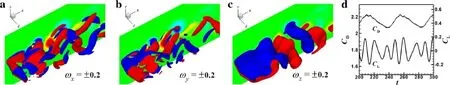
Fig.5 Isosurfaces of three components of vorticity,ωx,ωy,and ωz,in the near wake of peak-perforated conic shroud without separated plates at t=300 and time history of drag and lift coefficients in the same case as in Fig.4.Sectional contours of ωz at z=0 are shown in the background.Red and blue colors indicate positive and negative values

Fig.6 Isosurfaces of three components of vorticity,ωx,ωy,and ωz,in the near wake of peak-perforated conic shroud with separated plates at t=240 and time history of drag and lift coefficients in the same case as in Fig.4 with fine mesh

Fig.7 Isosurfaces of three components of vorticity,ωx,ωy,and ωz,in the near wake of peak-perforated conic shroud at t=220 in the same case as in Fig.6


Fig.8 Isosurfaces of three components of vorticity,ωx,ωy,and ωz,in the near wake at t=250 and time history of drag and lift coefficients in the case of Co:λ/D=4,W/λ =0.0125,Ag=45°,Do/D=0.1.Note that the body is shown using a semitransparent black surface and wire frame

Fig.9 Isosurfaces of three components of vorticity,ωx,ωy,and ωz,in the near wake at t=250 and time history of drag and lift coefficients in the case of Co:λ/D=6,W/λ =0.0125,Ag=0°,Do/D=0.4.Note that the body is shown using semitransparent black surface and wire frame
The relationships between these additional components of vorticity and the intensity of the geometric disturbance can be obtained theoretically;For example,in the case of a wavy square-section cylinder[38],the streamwise vorticity on the stagnation surface is linearly proportional to the slope of the waviness dξ/dz,which is proportional to the wave steepnessW/λ,while the vertical one increases in relation to 1+(dξ/dz)2.For the circular-section cylinder with radial disturbance[28],the former and latter relationships are designated as the radial and tangential components of vorticity in the cylindrical coordinate system,respectively,leading to more complex relationships between the streamwise and vertical components of the vorticity and the wave steepness.Generation of such additional components of vorticity and their transportation into shear layers and the near wake may lead to spatial redistribution of the vorticity and strain field with different intensities.The interaction between the streamwise or vertical and spanwise vortices or both coupled interactions and the flow perturbations due to the jet from the perforation introduced on the rear surface of a conic shroud result in different and complicated vortex shedding patterns,and even total suppression of Kármán vortices.Although some patterns were reported briefly by Lin et al.[28,31],the effects of a conic disturbance coupled with perforation introduced atitspeak are thoroughly investigated here and the different vortex shedding patterns summarized in detail.
3.1 Regime I(weak effect):Kármán vortices still shed alternately
Weak disturbance denotes that the additional components of vorticity themselves are very weak and quickly dissipated,accordingly having little effect on the shear layers.The spanwise vortex is shed almost uniformly along the spanwise direction,typically as shown in Figs.8 and 9.Therefore,the near-wake flow can still be described by an alternately shedding Kármán or Kármán-like vortex street in the wake of a 2-D circular cylinder,as shown in Fig.3a.
The time history of the drag and lift coefficients in this regime,as shown in Figs.8 and 9,is also similar to those in the basic 2-D case,as shown in Fig.3b.The peak amplitude of the lift,as well as drag,remains almost invariable with time.The order of magnitude of the peak amplitude of the drag coefficient is aboutO(10?2),the same as in the basic case.The oscillating frequency of fluid forces is thus unique.
Subregime I-A Kármán vortex without any obvious distortion,as shown in Fig.8.The additional components of vorticity are mainly generated on the front surface and are so weak that they dissipate promptly within the vortex formation region.Therefore,they have no influence on the upper and lower shear layers or the shedding spanwise vortices.
Subregime I-B Slightly distorted Kármán-like vortex,as shown in Fig.9.The intensified disturbance to some extent leads to small-scale vortices with additional compo-nents of vorticity generated and shed not only inside the vortex formation region but also with the shedding spanwise vortices.These vortices still dissipate quickly within a certain downstream distance;For example,for the present results shown by isosurfaces of three components of vorticityωx,y,z= ±0.2,this distance is about two inter-spanwise-vortex spacings in one row with the same sign.However,the weak interactions between the streamwise,vertical,and spanwise components of vorticity in the upper and lower shear layers lead to both the layers and shedding spanwise vortices becoming distorted and slightly wavy along thespan.

Fig.10 Isosurfaces of ωx,ωy,and ωz in the near wake at t=780 and time history of drag and lift coefficients in the case of Co:λ/D=6,W/λ =0.05,Ag=30°,Do/D=0.1
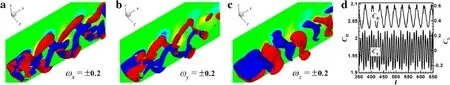
Fig.11 Isosurfaces of ωx,ωy,and ωz in the near wake at t=600 and time history of drag and lift coefficients in the case of Co:λ/D=6,W/λ =0.1,Ag=0°,Do/D=0.4
3.2 Regime II(moderate effect):alternately shedding spanwise vortices,obviously disturbed by additional vortices
In this regime with moderate disturbance effect,typically as shown in Figs.10 and 11,three basic features in the shear layers and near wake can be identified by comparison with those of the weak effect in regime I.
The second feature is the elongated shear layers,stretching downstream and being obviously distorted and wavy along the span.Owing to,at least,the strong interaction between the streamwise and spanwise vortices,as described in Ref.[21],both the top and bottom shearlayersvary distinctly along thez-axis with a wave shape,remaining apart from each other at the valley but being close at the peak.Consequently,the wake width increases at the valley but reduces at the peak.
The third feature is that,as a result of the wavy shear layers,the shedding spanwise vortices are distorted wavily and nonuniformly in the(y,z)plane.In spite of this,they still shed alternately downstream and almost maintain synchronization along the spanwise direction.
Subregime II-ASpanwise vortex distorted mainly by streamwise vortex pairs,as shown in Fig.10.It seems that this intensity of disturbance favors intensification of the streamwise vorticity.The relatively weak verticalvortex pairs almost dissipate early and rapidly(also within two intervortex spacings downstream of the vortex formation region for the isosurfaces ofωy= ±0.2).Therefore,the deformation of the spanwise vortices in the(y,z)plane cam mainly be attributed to the presence of streamwise vortex pairs.
In this subregime,the fluid forces vary with time but still maintain constant peak amplitudes,as shown in Fig.10.The peak amplitude for the drag is on the order ofO(10?3),obviously less than that for the basic 2-D case or the cases in regime I.This shows that the conic disturbance introduced here greatly reduces the oscillating amplitude of the drag.However,the same phenomenon,i.e.,the effect of perforation in slightly modifying the drag peak amplitude,also appears,with the same magnitude on the order of aboutO(10?4),varying with the same frequency as the shed vortices or oscillating lift force.
Subregime II-BSpanwise vortex distorted by both streamwise and vertical vortex pairs,as shown in Fig.11.The vertical vortices are further intensified,then shed throughout the whole computational domain,accompanied by shedding of streamwise vortices.Although the interaction between the vertical and spanwise vortices remains weak,the strengthened vertical vortices coupled with the streamwise vortices lead to shedding of spanwise vortices that are distorted more violently and wavily in not only the(y,z)but also the(x,z)plane,especially at a distance of one or two shedding periods downstream.For the present calculational parameters,this vortex shedding pattern,with a distorted spanwise vortex coupled with one pair of streamwise and vertical vortices of opposite sign alternately shed into the wake,is very similar to mode A in the 3-Dwake transition for a circular- or squaresection cylinder at moderate Reynolds numbers[33,37].
As shown in Fig.11,the time history of the fluid force coefficients is distinctly different from those presented above.The peak amplitude of the lift coefficient varies with time,showing great modification,e.g.,from a minimum of 0.15 to a maximum of 0.27 in Fig.11.However,the drag coefficient still fluctuates at around the same magnitude,with peak amplitude on the order ofO(10?2).Because of the longer period of oscillation of the drag,the main frequency of the drag is apparently lower than the main frequency of the lift or the vortex shedding frequency.Also,ignoring the time difference between the maxima of the drag and lift,the oscillating drag force increases or decreases almost simultaneously with the increasing or decreasing peak amplitude of the lift force,respectively.


Fig.12 Isosurfaces of ωx,ωy,and ωz in the near wake at t=620 in the same case as in Fig.11
It is noteworthy that such peak amplitude variations of the fluid forces with a longer period may be related to a physical phenomenon or to another vortex shedding pattern.In earlier work on the wake of a square-section cylinder with wavy stagnation face atR e=100[21],the flow in regime II(type B)clearly alternated between two distinct states with greatly varying oscillating peak amplitudes of the fluid forces.At the maximum drag and lift,the regime is mildly 3-D with small curvature in the spanwise vortices.However,at the minimum drag and lift,the wake becomes highly 3-D.Based on spectral analysis of the spanwise-averaged lift force,there are two distinct shedding frequencies and a beating frequency as the difference between them.It is anticipated that vortex dislocation orsplitting occurs to accommodate the spanwise variation in the frequency of vortex shedding,leading to this phase change.In work on the flow past a square cylinder at lower Reynolds numbers[33,39],the drag in the 2-D numerical simulations was greatly reduced after the 3-D wake transition,e.g.,mode A,in the 3-D computations.Also,the sectional drag force will be further reduced at positions where vortex dislocation occurs.Therefore,the present subregime actually consists of two distinct vortex shedding patterns.One consists of mildly distorted spanwise vorticesat lowerdrag and lift forces,as shown in Fig.11.The other comprises relatively less distorted spanwise vortices with higher fluid forces,as shown in Fig.,similar to subregime I-B.
3.3 Regime III(strong effect):complex vortex shedding patterns
For the strong disturbance effect,the main feature is that the original Kármán or Kármán-like vortex shedding totally disappears or only appears occasionally in coexistence with other,different vortex shedding patterns.This phenomenon can be related to the additional components of vorticity with complex spatial distributions and strength,being prominently different from those with regular signs observed under the moderate effect,and subsequently complicated interactions between the streamwise and/or vertical vortices and spanwise vortices.

Type A?-type vortex shed at the valley,as shown in Fig.13.Due to the complex interactions betweenωx,ωy,andωz,the resultant shedding spanwise vortex mainly adopts the?form,curved in the center of the valley and heading downstream,called the?-type vortex shed at the valley,similar to a hairpin vortex.
For this type,as shown in Fig.13,the time history of the drag and lift forces shows characteristics similar to those in regime I,with almost constant but smaller oscillation amplitudes at a single frequency for complete shedding of the?-type vortex.This indicates that the wake is fully involved in the alternate shedding of?-type vortex at the valley,referred to as the “pure”?-type vortex,in contrast to type B described next.
Type BAlternating transitions between the?-type vortex at the valley and the vortex shedding pattern with nearly 2-D characteristics,typically as shown in Figs.14 and 15.For certain control parameter values,similar to those in subregime II-B,the flow also presents two states and switches alternately between them.At lower drag and lift forces,the pure?-type vortex is shed at the valley.Meanwhile,the nearly 2-D spanwise vortex appears at higher fluid forces,similar to those in subregime I-B.This subregime thus seems to be a combination of subregime I-B and subregime III-A(type A).
Correspondingly,as shown in Fig.14,the main features of the time history of the fluid forces are also similar to those in subregime II-B,such as lower-frequency modulation with a longerperiod of wavy peak amplitudes and greatly oscillating amplitudes.
Moreover,another transitional pattern was also identified,as shown in Fig.16.At lower fluid forces,as shown in Fig.16 att=760,the?-type vortex is obviously shed at the valley.However,at higher fluid forces,as shown in Fig.16 att=840,the pattern is slightly different from the above,nearly 2-D spanwise vortex but similar to that in subregime II-A.In the nearwake,the spanwise vortex at the peak is always shed late,still having the features of the?-type vortex shed at the valley,but remaining nearly two-dimensional across the span once it is shed with the spanwise vortex at the valley.

Fig.13 Isosurfaces of ωx,ωy,and ωz in the near wake at t=900 and time history of drag and lift coefficients in the case of Co:λ/D=8,W/λ =0.05,Ag=30°,Do/D=0.1

Fig.14 Isosurfaces of ωx,ωy,and ωz in the near wake at t=470 and time history of drag and lift coefficients in the case of Co:λ/D=8,W/λ =0.0125,A g=0°,Do/D=0.4

Fig.15 Isosurfaces of ωx,ωy,and ωz in the near wake at t=500 in the same case of Co:λ/D=8,W/λ =0.0125,Ag=0°,Do/D=0.4 as in Fig.14

Fig.16 Isosurfaces of ωx(red/blue),ωy(yellow/green),and ωz in the near wake at different times and time history of drag and lift coefficients in the case of Co:λ/D=8,W/λ =0.025,Ag=0°,Do/D=0.4
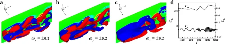
Fig.17 Isosurfaces of ωx,ωy,and ωz in the near wake at t=1200 and time history of drag and lift coefficients in the case of Co:λ/D=6,W/λ=0.2
In addition to these special characteristics of the vortex shedding pattern in the near wake,the fluid forces,as shown in Fig.16,are also different from those mentioned above in relation to Fig.14,in two respects:One is that the oscillating amplitudes of the drag and lift forces are greatly reduced to magnitude on the orderO(10?2);Another is the obviously wavy variation of the local maximum and minimum peak amplitudes of the fluid forces with time,associated with the two corresponding vortex shedding patterns.
Type C?-type vortex shed at the peak,as shown in Fig.17.Because it only appears for the conic cylinder,in the investigated parameter space,a brief introduction is presented in Ref.[28].In comparison with the?-type vortex shed at the valley,the obvious feature is that streamwise and vertical vortex pairs are so must greater or stronger in terms of both their spatial distribution and intensity that the shear layers are violently distorted upstream and greatly elongated even far downstream at the valley.Taking into account the spanwise vortices already shed downstream at the peak,the?-type vortex shed at the peak is described by a formation with its top orientated towards the center of the peak.The main difference from the pattern in type A is that the shedding spanwise vortices at the valley are distorted so violently that they are only distributed near the valley,and shed along with the spanwise vortices already shed at the peak.
As shown in Fig.17,the drag coefficient varied irregularly with time,almost without an obvious oscillating amplitude.The main physical reason for this is that the further elongated shear layers are only slightly influenced by the shedding of the?-type vortex at the peak.However,the lift coefficient varied intermittently with time between small and large oscillating amplitudes.
Subregime III-BCloud-like vortex:?-type vortices alternately shed at the peak and valley,as shown in Fig.18.The shear layers at the peak are stretched farther downstream than those in the?-type vortex shed at the peak or valley.Also,these shear layers vary wavily along both the streamwise and spanwise directions due to the complex distributions of the streamwise and vertical vortices,causing them to look like a cloud cluster,referred to as a “cloud”-like vortex in Ref.[28].
The time history of the drag and lift coefficients in this subregime,shown in Fig.18,reveals different characteristics,unlike the?-type vortex shed at either the peak or valley.The drag remains almost invariant with time,whereas the lift varies wavily with constant but smaller oscillating amplitude,indicating that the influence of the?-type vortex shed at the peak may be dominant.
Subregime III-CGreatly elongated shear layers:complete suppression of Kármán vortex shedding,as shown in Fig.19.This phenomenon is very similar to that occurring for the wavy square-section cylinder in Ref.[22].The present disturbance leads to a specific spanwise flow near the body,especially at the rear surface.This near-wall flow results in generation of vertical vorticity on the wall and oppositely signed vertical vorticity in the shear layers.Under the investigated control parameter values,this vertical vorticity is much larger than the streamwise vorticity,not only on the surface of the cylinder but also in both shear layers.Consequently,the flow behind the body is mainly turned around in the streamwise–spanwise plane,forming two recirculating regions in the near wake,rather than being traditionally translated downstream in the streamwise–vertical plane with Kármán vortex shedding.Due to this separation effect of the recirculation,the top and bottom shear layers cannot interact with each other and subsequently stretch far downstream.The wake flow becomes steady if perforation is not present.
Correspondingly,in the present subregime,as shown in Fig.19,the drag coefficient always remains constant with time,and the lift is zero due to the steady wake.
Subregime III-DMultiple vortex shedding patterns alternately appearing or coexisting with the?-type vortex.For the investigated computational parameter values,two other complicated multiple(at least three)patterns were identified,in addition to the typical?-type vortex shedding pattern described above appearing in the near wake as one of these multiple patterns.One is accompanied by an obliquely shedding vortex appearing as a competitive pattern.Another is followed by crossed spanwise vortices with opposite sign,only present as a transitional pattern in a series of successive vortex shedding patterns.
Type AOblique vortex shedding pattern coupled with?-type vortex shed at valley,typically as shown in Fig.20.The peak amplitudes of the fluid forces varied irregularly with time throughout the whole shedding period,obviously differing from the single or dual patterns alternately shed in the wake with regularly oscillating peak amplitudes of the drag and lift forces.Based on the appearance of different vortex shedding patterns in the wake,four stages were distinguished.Moreover,in each stage,the variation of the drag and lift forces with time was mostly regular:

Fig.18 Isosurfaces of ωx,ωy,and ωz in the near wake at t=200 and time history of drag and lift coefficients in the case of Co:λ/D=6,W/λ =0.2,Ag=0°,Do/D=0.1

Fig.19 Isosurfaces of ωx,ωy,and ωz in the near wake at t=700 and time history of drag and lift coefficients in the case of Co:λ/D=4,W/λ =0.2,Ag=0°,Do/D=0.2
Stage 1 In the first stage 350<t<900,as shown in Fig.20 att=400 and 420,the wake alternates between nearly 2-D spanwise vortices at higher fluid forces and the?-type vortex shed at the valley at lower fluid forces,just as in subregime III-A(type B).However,the local maximal peak amplitude of the drag gradually reduced with time,while the local minimal peak amplitude of the drag varied very little,indicating that the nearly 2-D vortex shedding pattern gradually disappeared in the near wake.Correspondingly,the peak amplitude of the lift was wavily reduced as time progressed.
Stage 2 In the second stage 900<t<1350,such as att=1300,there was only the pure?-type vortex alternately shed at the valley,exactly like the behavior in subregime III-A(type A).This stage can be considered to be a competitive result of the two patterns observed in the first stage,i.e.,total disappearance of the nearly 2-D vortex shedding pattern.Although the peak amplitude of the oscillating drag force remained constant,both the local maximum and minimum of the peak amplitudes of the drag actually increased very slowly with time,as did the peak amplitude of the oscillating lift force.
Stage 3 In the third stage 1550<t<1650,e.g.,att=1580,a new kind of vortex shedding pattern was observed at the lowest drag and lift forces.In complete contrast to the?-type vortex,the spanwise vortices,as well as the streamwise vortices,alternately shed asymmetrically along the span,called the obliquely shedding vortex.The typical oblique angle to the axis of the cylinder was about±38°,where positive and negative values denote slantwise angles to the positive and negativez-axis,respectively.In the case presented in Fig.20 att=1580,the oblique angle was positive,while a negative oblique angle appeared in the case of(Co:λ/D=8,W/λ=0.05,A g=45,Do/D=0.1).Note that the present obliquely shedding vortex is obviously different from the oblique mode of vortex shedding from a straight circular cylinder,the chevron pattern,and cellular shedding pattern in Refs.[37,40],in three main respects:The first is the instability of the present mode,which existed for only a short time period,in contrast to the stability of the oblique mode for the straight cylinder,which exists for a long time.The second is the greater oblique shedding angle,being about two times the latter oblique angles of15°?20°(or else break down along the span in the latter modes,if the oblique angle is too large).The third is the lack of end boundary conditions,because the latter modes are induced by manipulating the end(spanwise)boundary conditions.
Stage 4 In a competitive or coexisting stage 1350<t<1550,typically att=1410,the vortex shedding pattern in the near wake seems to be a combination of the pure?-type vortex and obliquely shedding vortex;For example,the spanwise vortex is already drag is rapidly reduced,as are the oscillating amplitudes of the fluid forces.

Here it should be stated that,for other control parameter values,e.g.,the case of(Co:λ/D=8,W/λ=0.05,Ag=45,D o/D=0.1),the main difference lies in the duration of each stage,especially the second,which becomes a transitional stage only existing for a very short time.

Fig.20 Time history of drag and lift coefficients and is osurfaces of ωx(red/blue),ωy(yellow/green),ωz in the near wake at different times in the case of Co:λ/D=8,W/λ =0.05,Ag=0°,Do/D=0.1
Type BCrossed spanwise vortices with opposite sign,interdigitated with each other,as shown in Fig.21.The time history of the fluid forces qualitatively looked like those in subregime II-B,with wavily varying peak amplitudes and low-frequency modulation.However,the oscillating amplitudes of the drag and lift are very large,approximately on the order of magnitude ofO(10?1)andO(1),respectively.In particular,the peak amplitude of the lift first gradually increased to amaximum,then quickly reduced to aminimum.Also,multiple vortex shedding patterns appeared successively in the near wake.
Stage 1 As shown in Fig.21 att=320,the?-type vortex alternately shed at the peak.
Stage 2 As time progressed up to 350,there was a transitional pattern from the former stage 1 into the next stage 3.However,it still has the features of an?-type vortex at the peak,with spanwise vortices already shed at the peak but still concentrated in the elongated shear layers at the valley.
Stage 3 When the time reached 390,the flow can be described by almost 2-D spanwise vortices shed alternately in the wake.
Stage 4 Att=400,the spanwise vortices in the wake were distorted,mainly by streamwise vortices,like those in subregime II-A.
Stage 5 As time increased to 410,the distortion of the spanwise vortices obviously became strong,similar to that in subregime II-B.

Fig.21 Time history of drag and lift coefficients and isosurfaces of ωx(red/blue),ωy(yellow/green),ωz in the near wake at different times in the case of Co:λ/D=8,W/λ =0.2,Ag=0°,Do/D=0.1
Stage 6 At time of 420,in strong contrast to the previous vortex shedding patterns,the spanwise vortices with positive sign extended slanting along the axis of the cylinder and upwards into the upper side of the wake aty>0,like a thorn,while the upper shear layer at the peak stretched downwards into the lower side of the wake aty<0 due to the strong streamwise vortices interacting with spanwise vortices,and the spanwise vortices with negative sign near the valley were still shed regularly into the wake.This pattern is called crossed spanwise vortices with opposite signs.Moreover,Fig.22 shows the spatial distribution of the spanwise vorticity in several typical spanwise sections,clearly indicating that the present streamwise vortices interacted with the spanwise vortices,strongly suppressing the spanwise vortex shedding at the peak,so the shear layers were therefore elongated downstream,as shown in Fig.22a,d.In the region 15<x<20,as the view moves from the end of the cylinder to its center,the periodic vortex wake pattern compromises the vortex pairs,just as in mode 2P of VIV in Ref.[2].In particular,Fig.22c seems to show that there is another vortex pair under the shear layers nearx=10.Comparison of Fig.22a–c also suggests that the spanwise vortex with positive sign in the upper vortex pair originates from the split spanwise vortex shed from the lower shear layer.
Stage 7 When the time reached 430,based on the features of the shedding spanwise vortices in the near wake,the present wake pattern can be described as?-type vortices alternately shed at the peak and valley.
Stage 8 Finally,at time of 440,the wake flow shows that the?-type vortex is about to shed at the peak,almost returning to stage 1.
In the same manner,the analysis above also shows that the wake is nearly 2-D at higher fluid forces but highly 3-D at lower fluid forces.Also,in the present case,during the fast decrease in drag from 390?t?430,the flow goes through the whole process from the weak to strong disturbance effect.Meanwhile,during the slow increase in drag from 320?t?390,the feature of the?-type vortex shed at the peak gradually disappeared in the near wake,and finally the flow was almost dominated by alternately shedding Kármán or Kármán-like vortices.
3.4 Overview of present parameter space
An overview of the simulations performed can be obtained based on this analysis of flow regimes for the parameter space 4?λ/D?8,0.0125?W/λ?0.2,and 0°?A g?45°only atDo/D=0.1,or0.1?D o/D?0.4 only atA g=0°,as shown in Figs.23b and 24a,respectively.It can be seen that the flow regime for most cases is independent ofAgorDo/D,and therefore similar to that without perforation,as shown in Fig.23a,especially for the cases atλ/D=6 orW/λ=0.2 and the main region of regime II(denoted by the dashed region).Only in some cases does the flow regime change due to the effect of the disturbance at variousA gorDo/Dvalues,particularly for the strong effect in regime III.As an example,Fig.24b presents a summary of the flow regimes atDo/D=0.4(A g=0°),showing that the region of moderate effect in regime II expands down to the region ofλ/D=4 andW/λ=0.1,and the subregime III-D(type A)at smallD o(?0.2D)evolves into subregime III-A(type B)atlargeDo(=0.4D)atλ/D=8 andW/λ=0.05;in other words,subregime III-A(type B)at small wave steepnessW/λ?0.025 expands up toW/λ=0.05 atDo/D=0.4.
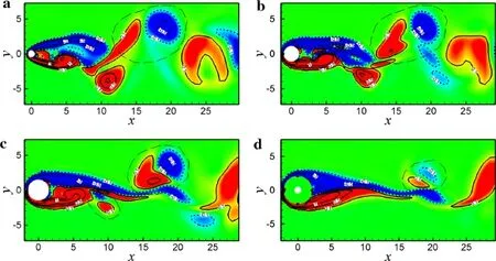
Fig.22 Contours of ωz at a z=0,b 3λ/(16 D),c 5λ/(16 D),and d λ/(2 D)for the case in Fig.21 at t=420.Red and blue colors,as well as solid and dashed lines,denote positive and negative signs for ωz,respectively.The region marked by long dashed lines indicates the “supposed”spanwise vortex pair on one side of the cylinder

Fig.23 Summary of flow regimes inλ/D versus W/λ for the cases of conic disturbances a without perforation and b with perforation for different Ag values at Do/D=0.1,where open diamond,open circle,and plus symbols denote regimes I,II,and III,respectively.Dashed lines are used to approximately separate different subregimes for most cases.The dashed region with/lines denotes subregime II-A,while the region withlines is the region where subregime II-B occurs.In b,some special cases at certain Ag marked by overlapping symbols are listed below:(1)at λ/D=4 and W/λ =0.1,subregime III-C only occurs at Ag=0°;(2)at λ/D=8 and W/λ =0.0125,subregime II-A only appears at Ag=0°;(3)at λ/D=8 and W/λ =0.05,the case of the subregime III-A(type A)indicated by times symbol only exists at Ag=30°
On the other hand,the different flow regimes of the conic cylinder and peak-perforated conic shroud clearly present two different effects,due to the conic disturbance in the former case and both the conic disturbance and peak perforation in the latter.As shown in Figs.23a,b and 24a,the similarity between the flow regions for the conic cylinder and peak perforated conic shroud in regimes I and II indicates that the effect of introducing the peak perforation is very weak,while the effect of the conic disturbance is generally dominant.However,in flow regime III,the wake flow behind the peak-perforated conic shroud is obviously different from that behind the conic cylinder in some cases,especially at higher wave steepness of 0.2.This indicates that the peak perforation effect becomes important.
Firstly,let us review the transition of the flow regimes for the conic cylinder only(without perforation)with increasingW/λand fixedλ/D,as shown in Fig.23a
(1)Forλ/D=4,subregime I-A?subregime I-B?subregime III-C
(2)Forλ/D=6,subregime I-B ? subregime II-A ?subregime II-B?subregime III-A(type C)
(3)Forλ/D= 8,subregime III-A(type B) ? subregime III-A(type A)?subregime II-B?subregime III-A(type C)
However,after the introduction of the perforation,as shown in Figs.23b and 24a,for differentAgvalues at fixedDo/D=0.1 andDo/D?0.2 with fixedA g=0°,respectively,the flow transition asW/λis increased for fixedλ/Dcan be generally viewed as follows

Fig.24 Summary of flow regimes in λ/D versus W/λ for the cases with a different Do/D and b Do/D=0.4 at Ag=0°,where open diamond,open circle,and plus symbols denote regimes I,II,and III,respectively.Dashed lines are used to approximately separate different subregimes for most cases.The dashed region with/lines denotes subregime II-A,while the region withlines is the region where subregime II-B occurs.In a,several special cases at certain Do/D with overlapping symbols are listed below:(1)at λ/D=4 and W/λ =0.025,subregime I-A with symbol times only occurs at Do/D=0.1;(2)at λ/D=4 and W/λ =0.1,subregime III-C appears at Do/D=0.1,subregime I-B at Do/D=0.2,and subregime II-A at Do/D=0.4;(3)at λ/D=8 and W/λ =0.0125,the case of subregime II-A only exists at Do/D=0.1;(4)at λ/D=8 and W/λ=0.05,only Do/D=0.4 indicated by symbol times is in subregime III-A(type B)
(1)λ/D=4,subregime I-A? subregime I-B? subregime III-C
(2)λ/D=6,subregime I-B?subregime II-A?subregime II-B?subregime III-B
(3)λ/D=8,subregime III-A(type B)(or subregime IIA)?subregime III-D(type A)? subregime II-B?subregime III-D(type B)
In particular,as an example of Fig.24b for fixedA g=0°andDo/D=0.4,the flow transition asW/λis increased for fixedλ/Dcan be viewed as follows
(1)λ/D=4 and 6,regime I(A or B)?regime II(A or B)?regime III(B or C)
(2)λ/D=8,subregime III-A(type B)? subregime II-B?subregime III-D(type B)
4 Conclusions
A numerical investigation was performed to understand the effects of introducing peak perforation on the conic disturbance of a VIV suppression shroud installed on a circular-section cylinder,mainly in terms of the vortex shedding pattern in the near wake and the time history of the fluid forces.The computations were carried out atR e=100 so that only a 2-D Kármán vortex street would appear in the near wake of the cylinder without any geometric disturbance.The wavelengthλand wave heightWof the conic disturbance,the angle of attack of the perforationAg,and the diameter of the holesD owere varied for fixed number of holes ofN o=4,uniformly distributed around the peak.From the viewpoint of the wake topology and force variation,these effects could be classified into 3 regimes or 11 subregimes for the investigated parameter space.
For the weak disturbance,regime I applies,where the effects due to both the conic disturbance and peak perforation are very weak.The wake behind the peak-perforated conic shroud was slightly 3-D,and the force history was very similar to that for the straight cylinder without any disturbance.In particular,for subregime I-B,as the wake vortex dynamics evolved further downstream,there was discernible deformation of the spanwise Kármán vortices associated with the shedding stream wise and vertical vortices.
When the disturbance became moderate,a transitional regime denoted as regime II occurred.In this regime,the effect due to the conic disturbance was mainly dominant while the effect due to the peak perforation remained weak.The top and bottom shear layers were stretched downstream with obvious spanwise curvature. Further downstream,streamwise and vertical vortices generated on the surface of the cylinder shed regularly with specific signs,associated with the mildly wavy deformation of the spanwise vortices.In subregime II-A,the drag and lift forces oscillated with constant amplitude in time at a single vortex shedding frequency.However,in subregime II-B,the peak amplitudes of the drag and lift varied wavily in a low-frequency modulation.Correspondingly,the wake topology alternated between a weakly 3-D state or nearly 2-D state at higher fluid forces and a mildly 3-D state at lower fluid forces.
Finally,when the disturbance was sufficiently strong,the classical Kármán or Kármán-like vortices partially or even totally disappeared in the wake,which is denoted as regime III.The peak perforation effect also became important in some cases,leading to the appearance of different vortex shedding patterns in the wake.In the first case,viz.subregime III-A,three types of wake flow were identified.Pure?-type vortices shed alternately at the valley with fluid forces oscillating with almost constant amplitudes was defined as type A.?-type vortices shed at the valley with nearly 2-D spanwise vortices appearing alternately with force history varying vialow-frequency modulation was defined as type B.?-type vortices shed at the peak with almost unvarying drag and little oscillating lift forces was defined as type C.Once the?-type vortex shed periodically and alternately at the peak and valley,called a cloud-like vortex,this regime wasdefined as subregime III-B,in which the drag remained almost constant and the lift oscillated with low amplitude due to the greater elongation of the shear layers downstream,therefore being less affected by the shedding vortex.In the third case,defined as subregime III-C,there was no evidence of a Kármán vortex wake,with only shear layers stretching very far away;the flow was almost steady with constant fluid forces.Moreover,multiple vortex shedding patterns appeared alternately or coexisted in the near wake,with complex variation of the fluid forces,being defined as subregime III-D.Two new patterns,viz.obliquely shedding vortex as a competitive pattern(type A)and crossed spanwise vortices with opposite signs as a transitional pattern(type B),were discovered,being mainly attributed to the peak perforation effect coupled with the strong conic disturbance.
For given wavelengthλand increasing wave heightWand varied angle of attackAgor diameter of holesD o,at small wavelengthλ?6D,the wake vortex dynamics generally evolved from regime I to regime III.However,when the wavelengthλwas increased up to 8D,the flow evolved firstly in regime III,then regime II,and finally back to regime III.
Many problems or unknowns regarding the flow around the presented peak-perforated conic shroud remain for future study.Comparison of the vortex shedding patterns and force history with those without perforation could help identify other features and effects of peak perforation.Frequency analysis of the time history of the drag and lift forces could be carried out using Fourier and wavelet methods.As mentioned above,regular distributions of additional components of vorticity with specific signs occur in the near wake,especially in regime II,and this phenomenon may also occur in flows around other kinds of bluff body.Furthermore,the theory of vortex-induced vortex(VIVor)could be proposed and used to explain such phenomena.Moreover,other methods could be proposed on the basis of the presented perforated conic shroud;For example,increasing the number of holes at the peak,or extremely adopting a slit at the peak rather than holes,and even covering the whole conic shroud with perforations,mainly near the peak,could be considered with the aim of further decreasing the oscillating fluid forces.
Acknowledgements This work was supported by the National Key Scientific Instrument and Equipment Development Program of China(Grant 2011YQ120048).
1.Sarpkaya,T.:A critical review of the intrinsic nature of vortexinduced vibrations.J.Fluids Struct.19,389–447(2004)
2.Williamson,C.H.K.,Govardhan,R.:Vortex-induced vibrations.Annu.Rev.Fluid Mech.36,413–455(2004)
3.Gabbai,R.D.,Benaroya,H.:An overview of modeling and experiments of vortex-induced vibration of circular cylinders.J.Sound Vib.282,575–616(2005)
4.Williamson,C.H.K.,Govardhan,R.:A brief review of recent results in vortex-induced vibrations.J.Wind Eng.Ind.Aerodyn.96,713–735(2008)
5.Owen,J.C.,Bearman,P.W.,Szewczyk,A.A.:Passive control of VIV with drag reduction.J.Fluid Struct.15,597–605(2001)
6.Huang,S.:VIV suppression of a two-degree-of-freedom circular cylinder and drag reduction of a fixed circular cylinder by the use of helical grooves.J.Fluids Struct.27,1124–1133(2011)
7.Korkischko,I.,Meneghini,J.R.:Suppression of vortex-induced vibration using moving surface boundary-layer control.J.Fluids Struct.34,259–270(2012)
8.Wu,H.,Sun,D.P.,Lu,L.,et al.:Experimental investigation on the suppression of vortex-induced vibration of long flexible riser by multiple control rods.J.Fluids Struct.30,115–132(2012)
9.King,R.,Brown,A.,Braaten,H.,et al.:Suppressing full-scale riser VIV with the VT suppressor.In:Proceedings of 32nd International Conference on Ocean,Offshore and Arctic Engineering(OMAE2013)(ASME),Nantes,France,June 9–14,OMAE2013-11642(2013)
10.Xu,F.,Chen,W.L.,Xiao,Y.Q.,et al.:Numerical study on the suppression of the vortex-induced vibration of an elastically mounted cylinder by a travelling wave wall.J.Fluids Struct.44,145–165(2014)
11.Lee,L.,Allen,D.W.:The dynamic stability of short fairings.In:Offshore Technology Conference Houston,Texas,USA,OTC-17125(2005)
12.Assi,G.R.S.,Bearman,P.W.,Kitney,N.:Low drag solutions for suppressing vortex-induced vibration of circular cylinders.J.Fluids Struct.25,666–675(2009)
13.Huera-Huarte,F.J.:On splitter plate coverage for suppression of vortex-induced vibrations of flexible cylinders.Appl.Ocean Res.48,244–249(2014)
14.Trim,A.D.,Braaten,H.,Lie,H.,et al.:Experimental investigation of vortex-induced vibration of long marine risers.J.Fluid Struct.21,335–361(2005)
15.Korkischko,I.,Meneghini,J.R.:Experimental investigation of flow-induced vibration on isolated and tandem circular cylinders fitted with strakes.J.Fluids Struct.26,611–625(2010)
16.Sarpkaya,T.,Isaacson,M.:Mechanics of Wave Forces on Offshore Structures.Van Nostrand Reinhold Company,New York(1981)
17.Kumar,R.A.,Sohn,C.H.,Gowda,B.H.L.:Passive control of vortex-induced vibrations:an overview.Recent Pat.Mech.Eng.1,1–11(2008)
18.Wu,H.,Sun,D.P.:Study on suppression measures for vortexinduced vibration of the deep water riser.China Offshore Platf.24,1–8(2009).(in Chinese)
19.Bearman,P.W.,Owen,J.C.:Reduction of bluff-body drag and suppression of vortex shedding by the introduction of wavy separation lines.J.Fluids Struct.12,123–130(1998)
20.Owen,J.C.,Szewczyk,A.A.,Bearman,P.W.:Suppressing Kármán vortex shedding by use of sinuous circular cylinders.Bull.Am.Phys.Soc.44,124(1999)
21.Darekar,R.M.,Sherwin,S.J.:Flow past a square-section cylinder with a wavy stagnation face.J.Fluid Mech.426,263–295(2001)
22.Lin,L.M.,Ling,G.C.,Wu,Y.X.:Mechanism responsible for the complete suppression of Kármán vortex in flows past a wavy square-section cylinder.Chin.Phys.Lett.27,034702(2010)
23.Lin,L.M.,Zhong,X.F.,Wu,Y.X.:Experimental investigation of a new device in suppressing vortex-induced vibrations of a circular cylinder.In:Proceedings of the Twenty-first International Offshore and Polar Engineering Conference(ISOPE),Maui,Hawaii,USA,June 19–24,1283–1288(2011)
24.Zhang,W.,Daichin,Lee,S.J.:PIV measurements of the near-wake behind a sinusoidal cylinder.Exp.Fluids 38,824–832(2005)
25.Lam,K.,Lin,Y.F.:Large eddy simulation of flow around wavy cylinders at a subcritical Reynolds number.Int.J.Heat Fluid Flow 29,1071–1088(2008)
26.Lam,K.,Lin,Y.F.:Effects of wavelength and amplitude of a wavy cylinder in cross-flow at low Reynolds numbers.J.Fluid Mech.620,195–220(2009)
27.Lin,L.M.,Zhong,X.F.,Wu,Y.X.:Vortex-induced vibrations of a circular cylinder with different geometric disturbances.In:Proceedings of the Twenty-second International Offshore and Ploar Engineering Conference(ISOPE),Rhodes,Greece,June 17–22,623–629(2012)
28.Lin,L.M.,Zhong,X.F.,Wu,Y.X.:Flow around a circular cylinder with radial disturbances at a low Reynolds number.In:Proceedings of Twenty-third International Offshore Polar Engineering Conference(ISOPE),Anchorage,Alaska,USA,June 30-July 5,387–394(2013)
29.Lin,L.M.,Zhong,X.F.,Wu,Y.X.:The drag,lift and Strouhal number of a circular-section cylinder with a conic disturbance at subcritical Reynolds numbers.In:Proceedings of the ASME 2014,33rd International Conference on Ocean,Offshore and Arctic Engineering(OMAE2014)(ASME),San Francisco,California,USA,June 8–13,OMAE2014-23017(2014)
30.Lin,L.M.,Zhong,X.F.,Wu,Y.X.:Characteristics for a flow past a circular cylinder with two types of radial disturbances atRe=100.Adv.Mater.Res.871,107–114(2014)
31.Lin,L.M.,Zhong,X.F.,Wu,Y.X.:Effects of a higher Reynolds number and introduced perforation on flows past the conic cylinder.In:Proceedings of the Twenty-Fifth International Ocean and Polar Engineering Conference(ISOPE),Kona,Big Island,Hawaii,USA,June 21–26,997–1003(2015)
32.Lin,L.M.,Zhong,X.F.,Wu,Y.X.:Effect of peak perforation on flow past a conic cylinder atRe=100:drag,lift and Strouhal number.China Ocean Eng.31,330–340(2017)
33.Lin,L.M.:Wake Dynamics and Forces in the Flow around the Square-section Cylinder with a Geometric Disturbance.[Ph.D.Thesis],Institute of Mechanics,CAS,Beijing,China(2007)(in Chinese)
34.Henderson,R.D.:Nonlinear dynamics and pattern formation in turbulent wake transition.J.Fluid Mech.352,65–112(1997)
35.Newman,D.J.,Karniadakis,G.E.:A direct numerical simulation study of flow past a freely vibrating cable.J.Fluid Mech.344,95–136(1997)
36.Roshko,A.:On the development of turbulent wakes from vortex streets.NACA Rep.1191(1954)
37.Williamson,C.H.K.:Vortex dynamics in the cylinder wake.Annu.Rev.Fluid Mech.28,477–539(1996)
38.Ling,G.C.,Lin,L.M.:A note on the numerical simulations of flow past a wavy square-section cylinder.Acta.Mech.Sin.24,101–105(2008)
39.Saha,A.K.,Biswas,G.,Muralidhar,K.:Three-dimensional study of flow past a square cylinder at low Reynolds numbers.Int.J.Heat Fluid Flow 24,54–66(2003)
40.K?nig,M.,Eisenlohr,H.,Eckelmann,H.:Visualisation of the spanwise cellular structure of the laminar wake of wall-bounded circular cylinders.Phys.Fluids A 4,869–872(1992)

- Acta Mechanica Sinica的其它文章
- Measurement of the flow structures in the wakes of different types of parachute canopies
- Mobile bed thickness in skewed asymmetric oscillatory sheet flows
- Mechanical properties of gas hydrate-bearing sediments during hydrate dissociation
- A modified multi-objective particle swarm optimization approach and its application to the design of a deep water composite riser
- Reliability-based multidisciplinary design optimization using incremental shifting vector strategy and its application in electronic product design
- Time-varying nonlinear dynamics of a deploying piezoelectric laminated composite plate under aerodynamic force