
Study of ionic wind based on dielectric barrier discharge of carbon fiber spiral electrode
2020-04-24 05:49WenzhengLIU劉文正WenlongHU胡文龍HaoZHAI翟浩ZhaoyangCUI崔昭陽andLuxiangZHAO趙潞翔
Plasma Science and Technology 2020年3期
Wenzheng LIU (劉文正),Wenlong HU (胡文龍),Hao ZHAI (翟浩),Zhaoyang CUI (崔昭陽) and Luxiang ZHAO (趙潞翔)
School of Electrical Engineering,Beijing Jiaotong University,Beijing 100044,People’s Republic of China
Abstract
Keywords:ionic wind,DBD,AC–DC coupled electric field,air purification
1.Introduction
The study of ionic wind has a long history,and Francis Hauksbee was the first to observe it in the early 18th century[1].Over the next two centuries,researchers established a preliminary theoretical explanation of the phenomenon.Normally,ionic wind is generated by a corona discharge.In a highly non-uniform electric field,the electric field strength in the vicinity of the generation electrode is sufficiently high to ionize air molecules.Driven by the Coulomb force in the electric field,charged particles generated by ionization accelerate toward the collection electrode.During the process of acceleration,the energy obtained by charged particles in an electric field is transferred to neutral gas molecules through collisions,giving rise to a bulk fluid motion—‘ionic wind’ [2].Since the generation of ionic wind has the characteristics of low power consumption and low noise,it has great potential for application in the fields of air purification,drying,cooling,airflow control and propulsion [3–10].
At present,the application of ionic wind is faced with two major difficulties:how to improve its speed and energy conversion efficiency.Some scholars have made certain achievements by optimizing the electrode structure.For instance,C Kim et al designed an ionic wind generator with a combined electrode structure,which obtained an energy conversion efficiency of about 1% and a stable volume flow rate of over 2000 l min?1[11].By using multistage linear array structures,and terminating in a converging nozzle,Richard et al managed to accelerate the wind speed by many times.[12].Lee et al increased the volumetric air flow by integrating multiple ionic wind generators and weakened the interaction between the generators by installing a PCB board on a multi-combination generator [13].R Tirumala and D B Go miniaturized the ionic wind generator,cut energy dissipation and boosted conversion efficiency by using a multielectrode assisted corona discharge [14].K Msuyama and S Barrett designed two types of EHD thrusters:one was singlestage(SS)and the other dual-stage(DS).The thrust-to-power ratio of the SS thruster went up to about 100 N kW?1,and the DS thruster proved to be more effective than the SS thruster[15].In addition to optimizing the electrode structure,some scholars increased the velocity of ionic wind by changing the discharge type,that is,by using a dielectric barrier discharge(DBD).For instance,Erfani et al accelerated the wind speed by DBD with an embedded multi-electrode composite structure [16,17].Thomas et al chose a thick dielectric medium with a low dielectric constant,which greatly increased the body force of the DBD plasma actuators [18].In order to improve the performance of the EHD propulsion system for space missions,Granados et al designed a single-stage EHD thruster at 1.3 kPa sub-atmospheric pressure[19].In previous lab research,W Z Liu et al used the micro-discharge characteristics of carbon fiber to effectively suppress the filamentous discharge,and realized a disperse glow discharge in atmospheric pressure air [20–22].On the basis of these results,this study will make use of the discharge characteristics of a carbon fiber spiral electrode and the AC–DC coupled electric field superposition mode to accelerate the velocity of ionic wind.
2.Electrode structure and experimental system
The electrode structure used in this study is a carbon fiber spiral electrode coupled with a metal rod electrode (hereafter referred to as coupled electrodes).A schematic diagram of the coupled electrodes is shown in figure 1,and the generation electrode is a carbon fiber spiral electrode where the carbon fiber is wound on an iron bar covered with polytetrafluoroethylene(PTFE).We select an iron bar with a diameter of 8 mm as the inner electrode of the spiral electrode,and the insulation layer on the inner electrode is 2 mm thick.The carbon fiber has a diameter of 1 mm,and the winding pitch is 15 mm.The diameter of the collection electrode is 2 mm and the spacing between the metal rods is 10 mm.The spacing between the generation electrode and the collection electrode is 20 mm.

Figure 1.A schematic diagram of the coupled electrodes.

Figure 2.A schematic diagram of the experimental system.
The experimental system consists of four parts:the aforementioned coupled electrode structure,a self-made high-frequency AC power supply,a DC power supply and measuring equipment,as shown in figure 2.The self-made high-frequency AC power supply has a frequency of 20 kHz,and the output voltage ranges between 0 and 10 kV.The DC power supply remains constant,with the amplitude ranging between 0 and 15 kV.The measuring equipment primarily includes a Tektronix high-voltage probe P6015A to measure the voltage between the electrodes,through which the voltage of two ends of a 100 Ω resistor in the AC series circuit is directly measured.The discharge current in the AC circuit can then be indirectly measured,and a Tektronix digital oscilloscope TDS1012B-SC displays the voltage and current signals.On the flank of the spiral electrode there is a Nikon digital camera COOLPIX P100 to photograph the discharge images.A Smart AR866A hot-wire anemometer is placed 10 mm behind the metal rod electrode to measure the ionic wind speed,which can be as accurate as 0.01 m s?1.

Figure 3.(a)Front view and side view of the electric field intensity distribution when only DC is applied to the coupled electrodes;I:front view,II:side view;(b) the electric field vector distribution when only DC is applied to the coupled electrodes.
3.Analysis of structure characteristics of coupled electrodes
3.1.Electric field distribution characteristics of coupled electrode structure
In the DBD process,the electric field distribution between electrodes is an important factor for the formation of the discharge,which determines the initial state of each of its cycles.Therefore,we choose the finite element analysis software ANSYS for the electric field distribution simulation analysis.When only DC is applied,the electric field distribution of the coupled electrode structure is obtained by ANSYS,and the results are shown in figure 3.In the simulation condition setting,no potential is added to the iron bar of the generation electrode,the carbon fiber is grounded,and the collection electrode is connected to a positive DC voltage of 12 kV.Figure 3(a) shows the electric field intensity distribution of the coupled electrode structure,with symbol I being the front view and symbol II being the side view.It can be seen from the figure that the electric field strength at the contact point of the carbon fiber spiral electrode is the largest,and is approximately in the range of 1.06×10⁶–2.3×10⁶V m?1.The electric field strength around the carbon fiber is strong,slightly larger than 1.06 ×10⁶V m?1,which is similar to the electric field strength around the collection electrode.The electric field strength in the middle region is weak,and is roughly in the range of 4.85×10⁵–7.17×10⁵V m?1.Figure 3(b) shows the electric field vector distribution of the coupled electrode structure.It can be seen from the figure that the direction of the electric field vector is from the collection electrode to the generation electrode,and the electric field vectors shrink to the carbon fiber.Due to the micro-discharge characteristics of the carbon fiber electrode,the gas molecules around the carbon fiber also have the possibility of undergoing impact ionization at a lower electric field strength [21].Hence it can be predicted that collisional ionization will first occur at the contact point of the carbon fiber spiral electrode,where charged particles generated from gas molecule collisional ionization can provide seed electrons for the area of weaker electric field strength around the carbon fiber,making collisional ionization possible at such a place.However,it is difficult for the gas molecules near the metal rod electrode to produce collisional ionization without providing seed electrons,so collisional ionization may only exist around the carbon fiber of the generation electrode,forming a weak corona discharge.The electrons and positive ions generated by the collisional ionization of the gas molecules around the carbon fiber will move in opposite directions under the action of electric field vectors.Eventually the electrons will reach the collection electrode and the positive ions will reach the generation electrode.Charged particles inevitably collide with neutral gas molecules in the process of moving,and transfer energy to neutral gas molecules through the collision.Just as the motion displacement of electrons and positive ions is quite different,so is the energy obtained from the electric field in the process of motion.Such an energy difference can cause the airflow to move in one direction,which may lead to the formation of ionic wind.

Figure 4.The electric field intensity distribution of AC–DC coupled electrodes;(a) AC +1.2 kV,(b) AC –1.2 kV.
Figure 4 shows the distribution of electric field intensity when the AC and DC are coupled.At this time,the iron bar of the generation electrode is applied with an alternating voltage of 1.2 kV,the carbon fiber is grounded,and the collection electrode is connected to a positive DC voltage of 12 kV.It can be seen from the simulation results that no matter whether the amplitude of the AC voltage is +1.2 kV or –1.2 kV,the red color at the contact point of the carbon fiber spiral electrode is obviously deepened compared with when DC only is applied;that is,the electric field intensity at the contact point of the carbon fiber spiral electrode is greatly enhanced when AC and DC are coupled.The electric field intensity on the outside of the carbon fiber increases dramatically,as shown in figure 4(a),while the electric field strength between the carbon fiber coils increases significantly as shown in figure 4(b).This is because the electric field strength at each point between the two carbon fiber coils is affected by the direction of the adjacent carbon fiber coils during the AC voltage changes.When the AC voltage is positive,the electric field vectors contract on the spiral coil,and when the AC voltage is negative,it diverges between the spiral coils.This is the result of the superposition of electric field intensity in multiple directions.However,this change is beneficial in order to avoid the vigorous development of the collisional ionization of gas molecules around the carbon fiber electrode,thereby effectively suppressing the occurrence of filamentary discharge.The middle region in figure 4(a) shows a green shift,while there is a yellow shift in figure 4(b),the factor being that the electric potential difference between the generation and collection electrodes changes from 10.8 kV to 13.2 kV when the AC voltage varies from positive 1.2 kV to negative 1.2 kV,and the electric field intensity in the middle region also changes accordingly.The electric field intensity of the carbon fiber spiral electrode is greatly enhanced by the electric field superposition method of AC–DC coupling,which is beneficial to promote the development of the collisional ionization of gas molecules around the carbon fiber.Furthermore,the periodic variation of the AC voltage can avoid the vigorous development of gas molecule collision ionization.Therefore,this approach will effectively increase the number of charged particles,thereby raising the speed of ionic wind.

Figure 5.(a)The spiral electrode discharge phenomenon in AC–DC coupled electrodes;(b) voltage and current waveforms in the AC circuit.
3.2.Electrical characteristics and wind speed characteristics of AC-DC coupled electrode structure
Figure 5(a) shows the discharge phenomenon of the carbon fiber spiral electrode in the AC–DC coupled electrode structure,where the amplitude of the AC voltage is 1.2 kV and that of the DC voltage is 12 kV.The ISO of the photograph is 200,the aperture value is f/2.8,and the exposure time is 1/2 s.It can be seen that a light blue discharge is generated on the carbon fiber spiral electrode and the whole carbon fiber is totally covered by plasma.Consistent with the previous analysis,the discharge is first generated at the contact point of the carbon fiber spiral electrode.Under the action of electric field vectors,a great number of charged particles generated from the contact point are dispersed to the area with a weaker electric field intensity around the carbon fiber to provide seed electrons,so that the discharge can occur in such a place.As the amplitude of AC voltage gradually increases,the discharge is accordingly enhanced,and finally the whole carbon fiber electrode is covered by plasma.The voltage and current waveforms of the corresponding AC circuit are shown in figure 5(b).It can be seen that the amplitude of current in the AC circuit is at millampere level,and the currents are not asymmetric in either the positive or negative half cycle of the voltage waveforms.The amplitude of the negative half cycle current is apparently bigger than that of the positive half cycle.The contributing factor is that the discharge of the carbon fiber spiral electrode is in the form of a single DBD,in the positive half period of the AC voltage,PTFE as an insulating medium can adsorb electrons and form an antielectric field,which can inhibit the development of electron avalanches.Furthermore,in the negative half period of the AC voltage,the electrons adsorbed on the PTFE are released as seed electrons,promoting the development of a negative half cycle electron avalanche.Thus it can be seen that the high-density plasma generated by the dielectric barrier discharge of the carbon fiber spiral electrode can provide a large number of charged particles for the formation of the ionic wind.
Figure 6(a)shows the relationship between the current in the DC circuit and the DC voltage when only DC and AC–DC coupling are applied separately.It can be seen that as the DC voltage increases,the current in the DC circuit increases in both cases.However,no matter how high the DC voltage is,the current in the DC circuit in the case of AC–DC coupling is obviously larger than that in the case where only DC is applied.In addition,as the DC voltage increases,the current in the DC circuit increases more significantly.The rising DC voltage causes the electric field strength around the generation electrode to increase,which intensifies the collisional ionization of gas molecules around the generation electrode and increases the number of electrons that flow through the acceleration region and eventually reach the collection electrode.Therefore,the current in the DC circuit increases.However,a dielectric barrier discharge is formed on the carbon fiber spiral electrode when AC and DC are coupled,while a corona discharge is formed on the carbon fiber electrode when DC is applied alone.Generally speaking,the density of plasma generated by the dielectric barrier discharge is higher than that generated by the corona discharge.Therefore,the number of electrons reaching the collection electrode at the same DC voltage is greater,and so is the resulting DC current.When the DC voltage is higher,charged particles generated by the dielectric barrier discharge are more likely to enter the middle region under the action of electric field vectors,thus the current in the DC circuit increases more significantly when AC and DC are coupled.Figure 6(b)shows the relationship between the ionic wind velocity and the DC voltage when only DC and AC–DC coupling are applied separately.Consistent with the relationship between the current in the DC circuit and the DC voltage,when the DC voltage increases,both the dielectric barrier discharge of the carbon fiber spiral electrode and the corona discharge of the carbon fiber electrode are enhanced,and more charged particles are generated;finally the velocity of the ionic wind increases.Since the number of charged particles generated by the dielectric barrier discharge is larger than that generated by the corona discharge under the same DC voltage,the speed of ionic wind generated by AC–DC coupled mode under the same DC voltage is larger than that when only DC is applied.The experimental result shows that the ionic wind velocity increases by 85% when AC–DC coupling is applied at the same DC voltage.
4.Optimization of AC-DC coupled electrode structure
4.1.Influence of carbon fiber spiral electrode pitch on ionic wind speed

Figure 6.(a) The relationship between the current in the DC circuit and DC voltage;(b) the relationship between the ionic wind speed and DC voltage.

Figure 7.The electric field intensity distribution of AC–DC coupled electrodes with different pitches:(a) pitch 15 mm,(b) pitch 10 mm,(c) pitch 5 mm.
The electric field simulation software ANSYS was used to simulate the electric field intensity distribution when the same voltages were applied to the AC–DC coupled electrode structure under different pitches,in which the AC voltage was set to 1.2 kV and the DC voltage was set to 12 kV.The results are shown in figure 7,where we can see that the smaller the pitch is,the more carbon fiber coils by unit of length there will be,resulting in a larger contact area between the carbon fiber and the iron bar.Therefore,when certain AC and DC voltages are applied at a time,a smaller pitch can form a larger area of high electric field strength.We can also see that the electric field intensity between coils decreases when the pitch becomes smaller,which is the result of the influence of other coils in all directions.The smaller pitch causes the larger influence of other coils in all directions,leading to a lower electric field intensity.Since it is difficult for the electric field intensity between coils to reach a degree of collisional ionization,the reduction of electric field intensity between coils will not have much impact on the dielectric barrier discharge of the carbon fiber spiral electrode.Through stimulation,we have come to realize that the area of high electric field strength increases as the pitch of the carbon fiber spiral electrode decreases.The increase in the area of high electric field strength will inevitably lead to a rise in the number of charged particles produced by collisional ionization,which is favorable for increasing the speed of ionic wind.
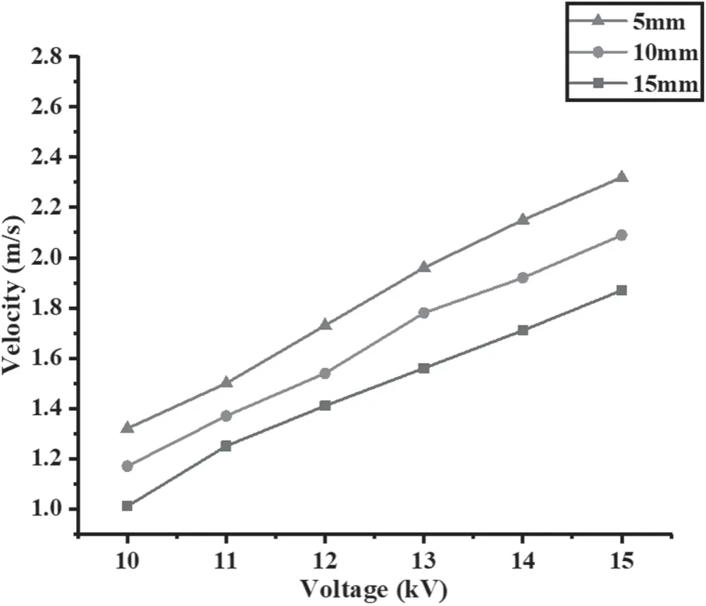
Figure 8.The relationship between ionic wind speed and DC voltage at different pitches.
The relationship between the ionic wind speed of the carbon fiber spiral electrode and the DC voltage under different pitches is shown in figure 8.It can be seen that the ionic winds of those three electrodes all increase as the DC voltage increases.The ionic wind speed formed by the AC–DC coupled electrode structure is the fastest with a pitch of 5 mm,followed by that with a pitch of 10 mm;that with a pitch of 15 mm is the slowest.As the pitch decreases,the contact area increases between the carbon fiber and iron bar with the same electrode length;when the same voltages are applied,the gas discharge area around the carbon fiber spiral electrode and the number of charged particles increase,which finally leads to an increase of ionic wind speed formed by the structure of the AC–DC coupled electrodes.
4.2.The strengthening effect of the third electrode on ionic wind speed
In the following,the dielectric barrier discharge of the carbon fiber spiral electrode increases the number of electrons used to form the ionic wind,and the ionic wind speed increases.On this basis,this section will further increase the number of electrons by means of electric field construction,and manage to achieve a further breakthrough in ionic wind speed.That is to say,a third electrode is added to the AC-DC coupled electrode structure to separate the generation of charged particles from the acceleration of charged particles.This means that charged particles are generated between the generation electrode and the third electrode (front),and the acceleration of charged particles occurs between the third electrode and the collection electrode (rear).Figure 9(a) shows the schematic diagram of adding a third electrode to the structure of the AC–DC coupled electrodes,where the distance between the third electrode and the generation electrode is 5 mm,and the distance between the collection electrode and the third electrode is 15 mm;the length of the carbon fiber spiral electrode is 30 mm,with a pitch of 5 mm.It is worth noting that the third electrode is composed of wires with an inner diameter of 0.6 mm and an insulation thickness of 0.2 mm.The electric field intensity distribution with a third electrode added to the AC–DC coupled electrode structure is shown in figure 9(b),where the iron bar of the carbon fiber spiral electrode is applied with an AC voltage of 1.2 kV,the carbon fiber is grounded,the collection electrode is connected to a DC voltage of 12 kV,and the third electrode is connected to a DC voltage of 5 kV.It can be seen from the electric field simulation that a strong electric field area is formed between the generation electrode and the third electrode,and the electric field intensity is maintained above 1.06×10⁶V m?1.On the premise that the carbon fiber spiral electrode provides seed electrons,this area has the possibility of undergoing collisional ionization.Figure 9(c) shows the electric field intensity distribution at line L before and after adding the third electrode.It can be seen that when the third electrode is added,the electric field intensity in the front increases significantly,but that in the rear decreases slightly.One contributing factor is that the addition of the third electrode changes the electric potential difference in the front and rear,increasing the electric potential difference in the front and decreasing the electric potential difference in the rear.In addition,because the distance between the generation electrode and the third electrode is small,while the distance between the collection electrode and the third electrode is large,the electric field intensity in the front increases significantly,while that in the rear decreases slightly.By adding a third electrode and reasonably controlling the voltage of the third electrode,the front part becomes the source of the charged particles and the rear part becomes the acceleration field.The sharp rise in the electric field intensity at the front causes the collisional ionization process to be more intense,increasing the number of charged particles substantially.However,the electric field intensity at the rear decreases slightly,having little impact on the acceleration process of the charged particles.Thus the addition of a third electrode to the structure of AC–DC coupled electrodes is conducive to the formation of ionic wind with a higher wind speed.
Figure 10 shows the relationship between the ionic wind speed and the DC voltage of the collection electrode before and after the addition of the third electrode to the structure of AC–DC coupled electrodes.As the collection electrode voltage rises,the wind speed increases gradually.This is because the addition of a third electrode makes the front and rear of the AC–DC coupled electrode structure the generation and acceleration area of the charged particles.The increase of the collection electrode voltage leads to the increase of the electric field intensity at the rear,which makes the charged particles at the front gain more energy in the DC acceleration area at the rear,forming an ionic wind with a higher speed.Compared with no addition of the third electrode,the ionic wind speed is higher under the same voltage condition.One contributing factor is that the electric field strength at the front of the AC–DC coupled electrode structure increases by adding the third electrode,and the ionization process is obviously enhanced,causing the charged particles to rise dramatically in number.Furthermore,because the slight reduction in the rear DC acceleration electric field has little impact on the velocity of the ionic wind,adding a third electrode to the structure of the AC–DC coupled electrodes and reasonably controlling its position and voltage can eventually result in the formation of ionic wind with a higher speed.The maximum ionic wind speed measured by the experiment was 2.98 m s?1.

Figure 9.(a) A schematic diagram of adding a third electrode to the structure of AC–DC coupled electrodes;(b) the electric field intensity distribution when the third electrode is added to the AC–DC coupled electrode structure;(c)the electric field intensity distribution at line L before and after the addition of the third electrode.
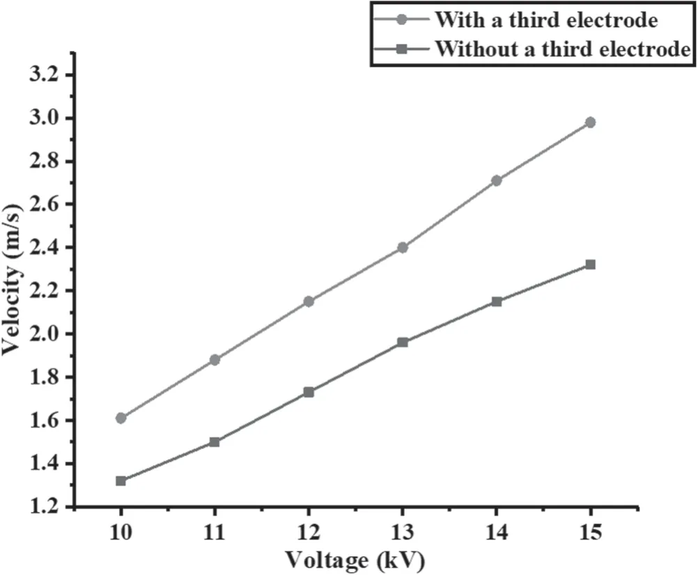
Figure 10.The relationship between ionic wind speed and DC voltage before and after the addition of the third electrode.
5.Conclusions
In this study,we have proposed a method for generating an ionic wind based on the dielectric barrier discharge of a carbon fiber spiral electrode by using a coupled electrode structure and an AC–DC coupled electric field superposition.Additionally,we have analyzed the formation process of ionic wind using simulation and experiment methods and achieved an enhanced ionic wind through adjusting the pitch of the carbon fiber spiral electrode and the design of the third electrode.The conclusions are as follows:
(1) By using the coupled electrode structure and adopting the AC–DC coupled electric field superposition method,the velocity of the ionic wind is increased by 85%.The AC dielectric barrier discharge of the carbon fiber spiral electrode provides charged particles for the formation of ionic wind,and the DC electric field provides the energy which is needed for its particle acceleration.
(2) By adjusting the pitch of the carbon fiber spiral electrode,it is found that the smaller the pitch is,the longer the carbon fiber wound on the spiral electrode will be under the same electrode length.A larger area of high electric field strength is therefore formed when AC and DC voltages are applied.This means that collisional ionization will generate more ionized particles,giving rise to an ionic wind of a higher speed.
(3) A third electrode with an insulation layer is added to the coupled electrode structure,which separates the collisional ionization process during the formation of ionic wind from the particle acceleration process.As the electric field gians more strength in the discharge region,the number of particles keeps rising and the ionic wind achieves an ever-higher velocity,with its maximum speed hitting 2.98 m s?1.
Thanks to the ability of the electrode structure to generate an atmospheric pressure DBD plasma and form an ionic wind,we can create a noise-free air purification device without resorting to a fan,with this device having good application prospects in the field of air purification.
Acknowledgments
This work is supported by National Natural Science Foundation of China (No.51577011).
 Plasma Science and Technology2020年3期
- Plasma Science and Technology的其它文章
- Three dimensional nonlinear shock waves in inhomogeneous plasmas with different size dust grains and external magnetized field
- Theoretical research on the transport and ionization rate coefficients in glow discharge dusty plasma
- Study on plasma cleaning of the large-scale first mirror of the charge exchange recombination spectroscopy diagnostic on EAST
- Decomposition of dioxin-like components in a DBD reactor combined with Hg/Ar electrodeless ultraviolet
- Measurements of plasma parameters in a hollow electrode AC glow discharge in helium
- Investigation of the self-induced magnetic field characteristics in a pulsed plasma thruster with flared electrodes