
Estimation of co-channel interference between cities caused by ducting and turbulence
2022-02-24 09:39KaiYang楊凱ZhensenWu吳振森XingGuo郭興JiajiWu吳家驥YunhuaCao曹運華TanQu屈檀andJiyuXue薛積禹
Chinese Physics B 2022年2期
Kai Yang(楊凱), Zhensen Wu(吳振森), Xing Guo(郭興), Jiaji Wu(吳家驥),Yunhua Cao(曹運華), Tan Qu(屈檀), and Jiyu Xue(薛積禹)
1School of Physics and Optoelectronic Engineering,Xidian University,Xi’an 710071,China
2School of Electronic Engineering,Xidian University,Xi’an 710071,China
With the rapid development of the fifth-generation (5G) mobile communication technology, the application of each frequency band has reached the extreme, causing mutual interference between different modules.Hence, there is a requirement for detecting filtering and preventing interference.In the troposphere, over-the-horizon propagation occurs in atmospheric ducts and turbulent media.The effects of both ducting and turbulence can increase the probability of occurrence of long-distance co-channel interference (CCI), in turn, severely affecting the key performance indicators such as system access,handover and drop.In the 5G era,to ensure communication channels and information security,CCI must be reduced.This paper introduces a scattering parabolic equation algorithm for calculating signal propagation in atmospheric ducts on irregular terrain boundaries.It combines Hitney’s radio physical optical model and Wagner’s nonuniform turbulent scattering model for calculating the tropospheric scattering in an evaporation duct or a surface-based duct.The new model proposes a tropospheric scattering parabolic equation algorithm for various tropospheric duct environments.Finally,as a specific case, the topographical boundaries between several cities in the East China Plain were considered, and the over-the-horizon propagation loss was simulated for various ducting and turbulent environments.The simulation results were used to evaluate whether CCI would occur between cities in a specific environment.
Keywords: atmospheric duct,tropospheric turbulence,co-channel interference,terrain parabolic equation
1.Introduction
The main cause of long-distance co-channel interference(CCI)is the atmospheric duct effect.Atmospheric ducts cause over-the-horizon propagation,thereby increasing the probability of crosstalk between long-distance communication signals.Studying the over-the-horizon propagation loss caused by this effect is important.The latest progress on the lower boundary of the duct has reached to the ducting propagation considering the boundary of the irregular terrain.On this basis,in this study,we consider the irregular terrain of the lower boundary of the duct to be the real topographic undulation distribution profile between cities.In addition, there are often turbulent motions in the troposphere,and the upper boundary of the duct involves tropospheric scattering caused by turbulence.This study combines these two boundary conditions to predict the over-the-horizon transmission of signals in atmospheric ducts to determine whether there is CCI between cities.
The parabolic equation method is the mainstream method for calculating the over-the-horizon transmission in the duct.In 1977, Tappert applied this method to acoustic propagation in the ocean.[1]In 1986, Ayasli proposed the SEKE model to calculate the propagation of low-altitude radar on nonuniform terrain, considering multipath effects, spherical earth diffraction, and multiwedge boundary diffraction loss.[2]In 1990,Levy applied the finite different scheme to solve the parabolic equation, making it suitable for radio wave diffraction on arbitrary terrain when the atmospheric reflection exists.Compared with the geometric diffraction theory, of which the terrain can only choose the idealized shape like knife-edge or wedges,the parabolic equation(PE)algorithm can directly input digital terrain.[3]In 1991, Kuttler and Dockery deduced the expression of the Helmohotz equation strictly converted from the spherical coordinate system to the rectangular coordinate system.They proposed the split-step Fourier transform(SSFT) method for solving the parabolic equation of atmospheric transmission on the impedance boundary of the earth’s surface.[4]In 1992,Barrios proposed a range-dependent environments model and applied it to the PE model to calculate tropospheric radio wave propagation.[5]In 1993, Yuan used the linear combination of odd and even functions to introduce the impedance boundary into the PE method,which overcame the restriction in the PE-SSFT scheme that it can only be applied on smooth surface boundaries.[6]In 1994, Barrios proposed the terrain parabolic equation model(TPEM)for tropospheric propagation based on the Fourier split-step scheme,assuming that the terrain boundary is perfectly conductive and smooth.Comparisons were made among the numerical simulation results of TPEM and other terrain models and the experimental data,and good agreements were obtained.[7]In 2000,based on the multiple mapping developed by Beilis and Tapert, Donohue and Kuttler applied the piecewise linear shift map method to the wide-angle PE model.[8]
The CCI phenomenon can be divided into close-range CCI between cells and long-distance CCI between cities.The long-distance CCI studied in this work is caused mainly by the occurrence of low-altitude ducts and turbulence effects.
In 1975, Dadson proposed timesaving computer programs to predict the field strengths from mobile radio base station transmitters and a method to facilitate frequency assignment in possible areas of co-channel interference.[9]In 1980,Gosling used a simple mathematical model to predict the effects of CCI and adjacent-channel interference in land mobile radio, and this model is applicable for flat urban terrains.[10]In 1995, Gao and Wong proposed a new adaptive method for CCI cancelation in the uplink of future multichannel communication satellite systems.This method does not require a reference signal and is suitable for phased-array and multibeam antennas.A modular cascade structure was developed for its implementation.Its performance was verified via computer simulations.[11]In 1999, Li and Sollenberger studied the parameter estimation problem of the least mean square difference set combiner when using an adaptive antenna array for interference suppression for orthogonal frequency division multiplexing(OFDM)systems with CCI problems.An improved parameter estimation method is proposed to effectively suppress the synchronous and asynchronous interference of packet and continuous data transmission in OFDM systems.[12]In 2010, Kohnoet al.proposed a CCI approach to eliminate the asynchronous spread spectrum in multiple access systems.CCI is considered the portion that can be regenerated at each receiver, and CCI problem can be eliminated by using linear algebra based on the known relationship between random noise sequences in all active channels.[13]In 2004, Liet al.proposed a method of using learning vector quantization to eliminate the CCI of burst transmission in a time-division multiple-access cellular mobile communication system.[14]In the same year,Zhanget al.studied the CCI processing method for downlink multicell user MIMO networks and proved that the base station cooperative processing capability was improved significantly even under severe CCI.[15]Later,Beaulieu determined the bit-error-rate performance of a new wideband effective pulse shape in the general fading and CCI environment.The new pulse has better bit-error-rate performance than the improved cosine pulse.[16]In 2006,Winters studied the optimal signal combination for spatial diversity reception of cellular mobile radio systems under CCI so that the system requires fewer base station antennas or achieves higher channel capacity through higher frequency reuse.In 2010,Quet al.discovered the phenomenon of long-distance CCI in radiowave over-the-horizon propagation and proposed solutions for different interference levels.[17]In the same year,Gulati reported the statistical physical modeling of CCI from the circular field of Poisson-distributed or Poisson-cluster-distributed interferometers.Further, by considering the interference distributed over the parametric ring region,an interference statistic of finite and infinite region interferences, with or without a guard region around the receiver,was obtained.[18]In 2013,Guptaet al.proposed a simple analytical model of important fading distributions such as the Weibull distribution and Nakagami distribution,and derived a closed solution of CCI for a linear interference distribution.[19]
The fifth-generation (5G) mobile communication technology will support a greater bandwidth, more connections and lower latency.The CCI problem will be more serious in a more complex base-station networking.At present, for the multicampus cellular system of the time division duplex(TDD) scale networking, the existing solution cannot accurately locate the source of the long-distance CCI.Therefore,further research on the evaluation, location, and suppression of long-distance CCI is necessary.Based on the analysis of the over-the-horizon propagation characteristics of radiowaves in a nonuniformly distributed atmospheric environment, that is,considering the existence of ducts and nonuniform turbulence phenomena, we studied the over-the-horizon propagation of electromagnetic waves in irregular terrain between cities,and analyzed the long-distance CCI in mobile communication.
2.Long distance CCI communication
In the TDD wireless communication system, under certain climatic, terrain and environmental conditions, the propagation of wireless signals exhibit an atmospheric ducting effect.Electromagnetic waves perform over-the-horizon propagation within the trapping layer of the duct.
Although the design of the guard period(GP)in the frame structure of a TDD system provides protection against longdistance interference at a certain distance, long-distance CCI may still occur in commercial TDD systems.The possible reasons are that the physical distance is relatively large or that the interference source signal has undergone repeated refractions and reflections to produce similar interference in the form of multipath propagation.
In the case of large physical distance, when the remote base station is within the atmospheric duct layer as the emission source, the high-power downlink signal of the remote base station reaches the disturbed base station through longdistance transmission.The long-distance transmission time is long, and the transmission delay exceeds the GP in the TDD system.This causes the downlink(DW)signal of the remote base station to fall within the uplink (UP) time slot of the nearby base station,causing CCI in the TDD system.
Figure 1 shows a schematic diagram of frame interference in a TDD system.In the case of a strong duct,the longdistance and small-attenuation transmission of the co-channel signal over an ultra-long distance causes cross-slot interference of the TDD,that is,the DW interferes with the UP on the special subframe and the uplink U subframe.
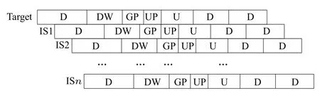
Fig.1.Frame interference schematic diagram.
2.1.The cause of long-distance CCI
The main factors that produce long-distance CCI are the atmospheric duct effect and the tropospheric scattering effect.Under special climatic conditions, electromagnetic waves are trapped in the duct layer and scattered at the top of the duct layer.The signals propagate far beyond the line of sight with small propagation losses.
The troposcatter propagation mode can travel more than 1000 km because of many vortex-like turbulent air masses formed by air in the troposphere.The spiral turbulent air mass is equivalent to a passive transmitting antenna that can reflect the electromagnetic wave transmitted by ground transmitters to distant places.Figure 2 shows the trans-horizon transmission between different cities due to the tropospheric scattering propagation mode.The tropospheric scattering effect may occur at any time and is affected greatly by meteorology.The propagation field strength in summer is larger than that in winter,and in the morning and night is larger than that in the noon.The troposcatter effect is more obvious for signals above 100 MHz.
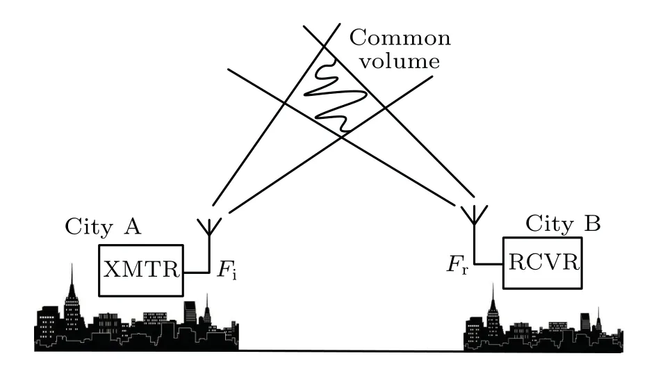
Fig.2.Tropospheric scattering mode.
The maximum propagation distance of the atmospheric duct propagation mode is the sum of the theoretical distance and 100 km of the line-of-sight propagation distance.The principle of this mode is that the electromagnetic waves in the very high frequency (VHF) and ultra high frequency (UHF)bands refract repeatedly in the duct layer owing to the different atmospheric temperature, pressure and water vapor distributions.These refractions cause the bending of the propagation path to change, and form a good channel for radio propagation.This type of propagation is called the atmospheric duct propagation.Figure 3 shows the tropospheric duct propagation mode.

Fig.3.Tropospheric duct propagation mode.
After over-the-horizon propagation, the high-power downlink signal of the remote base station located at a certain height is transmitted to the nearby base station through long-distance propagation.Since the long-distance propagation time exceeds the GP between the uplink and downlink in the TDD system,the downlink signal of the distant base station is received by the near base station at the receiving time slot of the nearby base station, thereby disturbing the uplink reception of the nearby base station,and resulting in long-distance CCI in the TDD system.
2.2.Positioning of interference sources and schemes for processing CCI
The current evaluation scheme of long-distance CCI is mostly actual measurement.The process is complicated,timeconsuming and laborious.In this work,we modeled the overthe-horizon transmission loss caused by a tropospheric duct and tropospheric nonuniform turbulence, and evaluated the long-distance CCI from the long-distance propagation loss.
Figure 4 shows the principle of CCI caused by over-thehorizon propagation.During the propagation, the signal may encounter various media environments such as vegetation,bare soil and freshwater areas on the path between cities.So long as the transceiver antenna is located in the duct-trapping layer,over-the-horizon propagation of signals may occur.Under the influence of complex lower boundary conditions and turbulence effects,CCI may occur between cities.
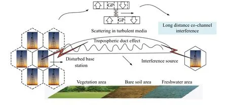
Fig.4.Cochannel interference caused by over-the-horizon propagation.
The current technology to locate the CCI source is difficult to implement.In particular,according to the characteristics of the frame structure in the time division-long term evolution (TD-LTE) system and the possibility of intercell interaction information, it is determined whether the interference received by the base station in the TD-LTE system is from the downlinks of a co-channel base station at a distance.Then,the interference source can further be located.
The characteristics of the frame structure are only one aspect of the TD-LTE system to circumvent such interference.To locate the long-distance CCI source in the TDLTE system specifically, it is necessary to determine whether the nearby base station in the TD-LTE system is subject to long-distance CCI, to determine the CCI source location, and to take measures to reduce CCI.In addition to the schemes proposed in this paper, the current evaluation methods for the long-distance CCI, positioning interference sources,and interference-resolving techniques are available in literature.[17]
3.Tropospheric atmospheric duct
3.1.Parabolic equation algorithm
At radiowave frequencies(below 100 GHz),the propagation in the atmosphere is affected mainly by oxygen and watervapor molecules.To a very good approximation,the air can be considered as a non-dispersive medium for radio frequencies.The real part of the radio-refractive index is then given by the Debye formular[20]
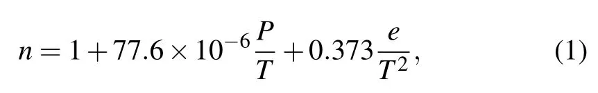
wherePis the atmospheric pressure in millbars,Ttemperature in Kelvin andewater vapor pressure in millbars.
The atmospheric refractive index remains very close to unity.Surface values ofn, which are usually strongest and vary rarely exceed 1.0004 or so.It has become customary to use the refractivityN,[21]which is defined by
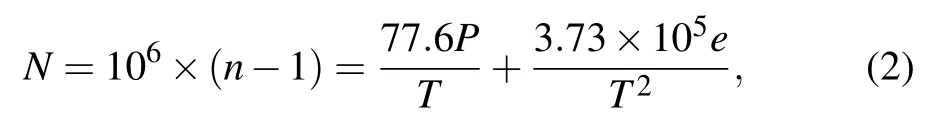
where the refractivityNis expressed in N-units.
In general, the refractivity of tropospheric,N, mostly changes in units of 250–450 N-units.As the height increases,temperature decreases slowly,while atmospheric pressure and water vapor pressure decrease rapidly,causing the refractivity to decrease with height gradually.Because of changes in the meteorological environment,temperature and humidity inversions occur frequently, resulting in abnormal refractivity gradients that lead to the formation of an atmospheric duct.
The evaporation of seawater vapor causes an abnormal decrease in humidity with increasing height,possibly forming an evaporation duct over the sea.The advection and sinking motions of the air, resulting in an abnormal increase in temperature with increasing height, often lead to the formation of a surface duct or an elevated duct.When the atmospheric refractivity gradient is less than a certain threshold, that is,dN/dh< ?0.157 N unit/m, the electromagnetic waves are trapped and refracted within a certain height, causing overthe-horizon propagation in the atmospheric duct.
Considering that a signal forms an over-the-horizon propagation in the duct layer, the distance is far enough that the curvature of the Earth must be considered.Then,the corrected refractive indexmis expressed as follows:
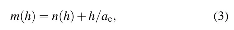
wherehis the height in km of the calculated point from the ground, andaeis the average radius of the Earth in km(6371 km).Then, according to the above formula, the corrected refractivityM(M-units)is as follows:

The parabolic equation algorithm is used to calculate the propagation characteristics of radio waves in a complex atmospheric environment on a nonuniform surface.According to Maxwell’s equations,the electromagnetic wave signals are assumed to propagate in thex-direction,regardless of the influence of they-direction, and thez-direction is the height direction.The refractive indexnof the propagation medium is isotropic.Considering only forward propagation and using Feit–Fleck approximation for the pseudo differential operator,the wide-angle parabolic equation can be expressed by[22]
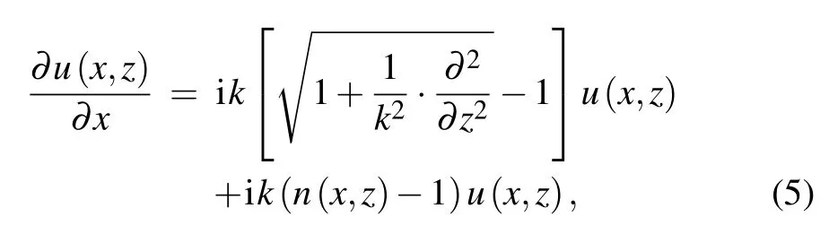
wherek0=2π/λ is the electromagnetic wavenumber depending on the wavelength of the electromagnetic wave.Further,u(x,z)is an electric field component or a magnetic field component,and the wide-angle parabolic equation can be used to theoretically calculate the over-the-horizon propagation within a radar elevation angle of 30°.
3.2.WAPE based on piecewise linear topographic shift map
When studying CCI caused by over-the-horizon propagation between actual cities, it is necessary to consider the influencing factors on the lower boundary of the region, that is, the nonuniform surface.This problem is solved by using the piecewise linear terrain shift map[8]proposed by Donhueet al.Based on the continuous terrain shift map[1]proposed by Beilis and Tappert, the piecewise linear terrain shift map uses the slope of the terrain instead of the curvature of the terrain for the parabolic equation.This helps remove the defects of the Beilis–Tappert’s continuous terrain shift map algorithm whose terrain curvature is difficult to obtain.
Beiliset al.considered the terrain calculation of the parabolic equation based on the coordinate transformation method.In this method, a new coordinate system is established on a nonuniform surface, and the propagation of electromagnetic waves is transformed in the presence of ducts and turbulence to a flat ground form through coordinate transformation.The parabolic equation is now expressed as follows by using a coordinate transformation and approximation method:
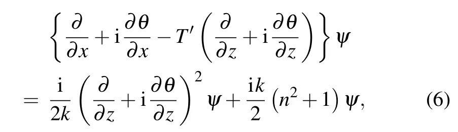
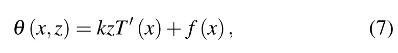
wherekis the wavenumber,nis the refractive index andTrepresents the slope of the terrain.The field components are expressed in a simplified form as φ(x,z) = exp(iθ)ψ(x,z)in the new coordinates.This formula is a parabolic equation corresponding to the Beilis–Tappert continuous terrain shift map approach.Let the derivative of the phase function be?θ/?z=kT′,that is,
wheref′(x) =k(1+T′)/2.Based on this derivation, the wide-angle parabolic equation in the new coordinate system is obtained as follows:
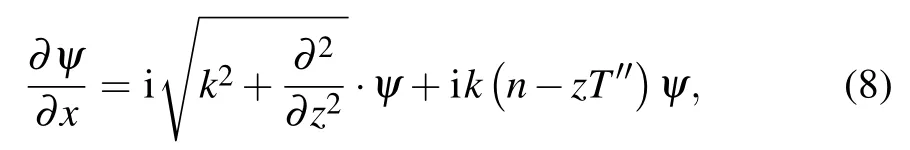
whereT′′is the curvature of the terrain, expressed asT′′=d2T(x)/dx.IfT′′=0,the terrain is flat,and the above equation becomes a parabolic equation with a wide angle on flat ground.
However, the actual topographic curvature is difficult to obtain, and the phase factor is considered according to Donhueet al.as follows:
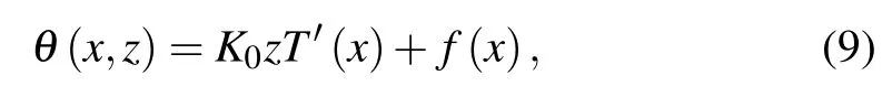
wherek0is a constant.Substituting Eq.(9) into the forward parabolic equation,with approximation,we obtain the following equation:
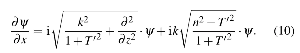
The above formula is a wide-angle parabolic equation(WAPE)of the piecewise linear topographic shift map approach.In this formula, the terrain slopeT′is used instead of terrain curvatureT′′used in Beilis–Tappert continuous topographic shift map approach.
3.3.Hitney’s radio optical model
In addition to tropospheric ducts, tropospheric scatter caused by atmospheric turbulence is an important factor affecting the over-the-horizon propagation.Hitney proposed a simple method to explain the troposcatter using the parabolic equation of the radio physical optical model.He proposed a hybrid scattering model, the radio physical optics (RPO)model,[23]combining ray optics with parabolic equations.This RPO model is suitable for evaluating the tropospheric effects of distances in the frequency range of 100 MHz to 20 GHz.This method can be used to calculate the tropospheric scattering problem caused by atmospheric turbulence by using the PE method in a simple and effective way.In the meantime,it avoids the problem that turbulence is ignored when the turbulence scale is smaller than dzin the phase screen method.
PE can predict the propagation loss caused by diffraction and other problems well.Although the loss caused by tropospheric scattering is far less than that caused by diffractions,the combination of the two has a great influence on the application of communication and interference.
In the RPO model, the scattering effect is modeled as a series of random and uncorrelated microlayered layers superimposed on the mean refraction field.The one-dimensional refractive index profile is described as follows according to Gossard:[24]
where the effective median structure constant is defined by Doviak as[25]
whilezis the sea surface height in m,andkis the dimensionless wavenumber.
The RPO model adds the refractive index perturbation caused by atmospheric turbulence to each step of the atmospheric corrected refractive index profile.The atmospheric refractive index profile considering random stochastic refractive index is expressed as

whereniis the refractive index in the PE model without considering the tropospheric scattering, andnfis the random refractive index perturbation caused by tropospheric scattering
whilerrandis a random number that is uniformly distributed by a parameter of(0,1),and the corrected refractivity considering the curvature of the earth is expressed as

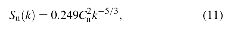
The global positioning system (GPS) L1 band signal(1.57542 GHz)is used to test the path propagation loss distribution of electromagnetic waves in the standard atmosphere,evaporation duct and surface duct environments under the influence of tropospheric scattering.The simulation results are shown in Figs.5–7.The test parameters are as follows: the height of the transmitting antenna is 13 m in the standard atmosphere and evaporation duct,and 60 m in the surface duct.The transmitting radar is horizontal polarized.TheM-profile of the evaporation duct is simulated by using the classical single-parameter Paulus–Jeske (PJ) model.The evaporation duct height is 13 m, and theM-profile of the surface duct is simulated by using a tri-folded four-parameter model,[26]which is expressed as [40 40 0.12 ?0.2].The wavenumber width is 3°.The emission elevation angle is 0°.The maximum propagation angle is 4°.The number of Fourier transform point is 213.The sea surface electromagnetic parameter is 70+5i.The lower boundary is assumed to be an ideal impedance boundary condition.
Figure 5 shows the spatial distribution of the propagation loss in the standard atmosphere and the propagation loss vs.distance at the antenna height.Figure 6 shows the situation in evaporation duct environment, and Fig.7 shows the situation in surface duct environment.
Fig.5.(a)Propagation loss in standard atmosphere without turbulence,(b)propagation loss in standard atmosphere considering turbulence,(c)comparison of propagation loss vs.distance at antenna height with and without turbulence.
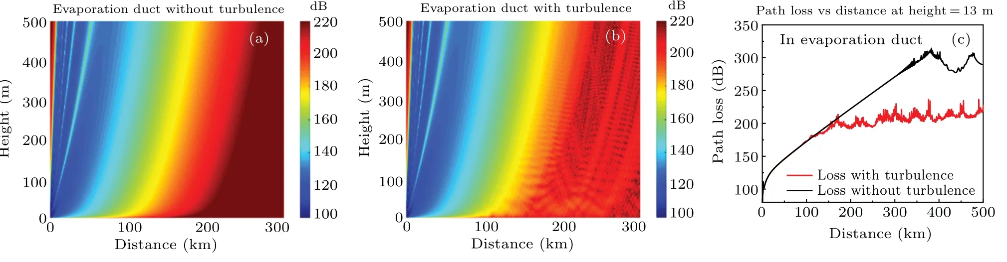
Fig.6.(a) Propagation loss in evaporation duct without turbulence, (b) propagation loss in evaporation duct considering turbulence, (c)comparison of propagation loss vs.distance at antenna height with and without turbulence.
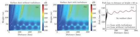
Fig.7.(a)Propagation loss in surface duct without turbulence,(b)propagation loss in surface duct considering turbulence,(c)comparison of propagation loss vs.distance at antenna height with and without turbulence.
Figures 5(a)and 6(a)illustrate the enhancement effect of atmospheric duct on over-the-horizon propagation of electromagnetic wave signals.Figures 5(c)and 6(c)jointly illustrate the significant influence on the over-the-horizon propagation of signal caused by tropospheric scattering.In the simulation,we assume the lower boundary is perfect electric conductor.It is shown from Figs.5(c) and 6(c) that in the near propagation distance, the difference between the propagation loss in atmospheric duct with or without turbulence considered is little, with the increase of propagation distance, and the turbulence decreased the path loss obviously.The tropospheric scattering we considered here is mainly in the ducting layer.It is reasonable to assume that when signals propagate in the ducting layer, the tropospheric vortex makes the scattering at the upper boundary of ducting layer stronger.So when the tropospheric scattering is considered,signals in the ducting layer could transmit farther.
In addition,the surface-based duct is simulated according to Hitney’s RPO model.The simulation results in Fig.7 show that for surface-based duct, the model simulating the tropospheric scattering has little effect on over-the-horizon propagation.This is related to the effective median structure constant chosen in the RPO model.According to Eq.(11),defined by Doviak has a negative exponential relationship with the height.The power could approach 1 so long as the top height of the duct layer is high enough.This leads to a constant itemin the surface-based duct, which cannot effectively simulate the influence of the troposcatter on the surface-based duct top layer.In response to this, Wagneret al.proposed a new effective median structural constant form,taking into account the base layer height and the thickness of the duct layer.This form is more consistent with the meteorological conditions of the actual turbulent stratified motion.By combining Hitney’s RPO model with Wagner’s nonuniform turbulence model, a new scattering parabolic equation model for low-altitude ducts and high-altitude tri-folded ducts was obtained.
3.4.Nonuniform turbulence model
The effective median structure constant assumed by the RPO model is simple in form and has no strong correlation with the duct height of the inversion layer.However,the marine atmospheric boundary layer(MABL)witnesses turbulent stratified movement.When fully developed,the MABL is divided into the surface layer, mixed layer and inversion layer under the free troposphere.The stress and horizontal pressure gradients between the layers are balanced to ensure a constant mass of MABL.Because of the balance between the two,we are unable to determine the turbulence scale of the mixed layer and the inversion layers easily.[27]However, eddy displacement effect ensures that the water vapor content in the air approaches the horizontal mean properties at nearby heights.According to the expression of the refractive index in Eq.(1),water vapor is the main factor controlling the change in the refractive index.The larger the water vapor gradient,the larger is the variance in the height of the layer.Hence,the refractive index change caused by the inversion layer with a large water vapor gradient is much larger than that of the mixed layer.
According to Gilbertet al.,(z)can be increased by more than 10 times in the inversion layer of a duct,[28]that is,varies over height when there is a duct, reaching a maximum in the middle of the inversion layer, and returning to a nearly constant value above the duct.In response to this, Wanger and Gersoftet al.proposed a nonuniform turbulence model for modeling the effective median constants with changes in height for actual meteorological phenomena.This model simulates the increase innear the middle of the inversion layer in a duct
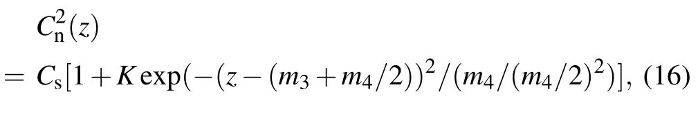
whereCsrepresents the reference value of,m3andm4are the base height and thickness of the duct,respectively,andKcan be adjusted to give any desired maximum to the function.Based on the model, the refractive index profile in a nonuniform turbulence environment can be calculated by using the following formula:

This formula roughly simulates the effect of the actual turbulent meteorological environment on the refractive index as a function of height.Gerstoftet al.suggested that only a surface-based duct will cause the propagation of the propagating wave between duct height and the Earth’s surface.[29]Assuming that the medium is quasiuniform[30](i.e., the formula does not consider changes in the dielectric properties of the medium), Eq.(17) can be used to determinenih(z)accurately.[31]
For a surface-based duct and an elevated duct, GPS signals were used to test the results of Wagner’s nonuniform turbulence model and Hitney’s RPO model.GPS L1 band signal was used,wheref=1.57542 GHz.The transmitting antenna height was 60 m for the surface-based duct and 100 m for the elevated duct.Parameters in the tri-folded four-parameter model of the surface-based duct are [40 40 0.12 ?0.2].Parameters of the tri-folded four-parameter model of the elevated duct are [80 100 0.118 ?0.118].The remaining parameters are the same as above,and the propagation losses for the two duct profiles in the RPO model with the nonuniform turbulence model are shown in Figs.8 and 9 for comparison.
Fig.8.(a) Spatial loss distribution calculated by the RPO model in a surface-based duct, (b) spatial loss distribution calculated by the nonuniform turbulence model in a surface-based duct,(c)path loss vs.distance at 60 m height between the RPO model and nonuniform turbulence model.
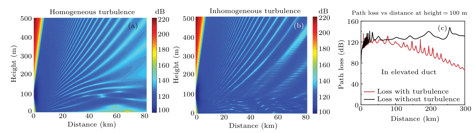
Fig.9.(a)Spatial loss distribution calculated by the RPO model in an elevated duct,(b)spatial loss distribution calculated by the nonuniform turbulence model in an elevated duct,(c)path loss vs.distance at 60 m height between the RPO model and nonuniform turbulence model.
Comparison of the RPO results in Fig.7 with the results shown in Figs.8 and 9 shows that,the nonuniform turbulence model has well simulated the tropospheric scattering effect of the inversion layer, and the over-the-horizon propagation of the surface-based duct and elevated duct are enhanced.Therefore, by combining two troposcatter models, we proposed a new scattering parabolic equation model for evaporation duct,surface duct and elevated duct environments.
4.Over-the-horizon propagation under nonuniform surface boundaries
4.1.Description of terrain links between different cities
Combining the new scattering parabolic equation model(considering tropospheric scattering)and the piecewise linear topographic shift map(considering the actual terrain), we established a scattering parabolic equation model considering nonuniform turbulence and different duct environments on a nonuniform terrain.
According to the communication data given by China Mobile in 2008,the problem of over-the-horizon propagation has caused serious CCI in the plains or open areas around the east of China,especially near Taihu Lake(116°E,30°N).After heavy rainfall,the terminal signal cannot be often accessed.[32]The area where CCI often occurs between the path links of several cities in the east of China region of Taihu Lake was analyzed for simulating the over-the-horizon propagation problem.An overview of the satellite map of the region around Taihu Lake is shown in Fig.10.
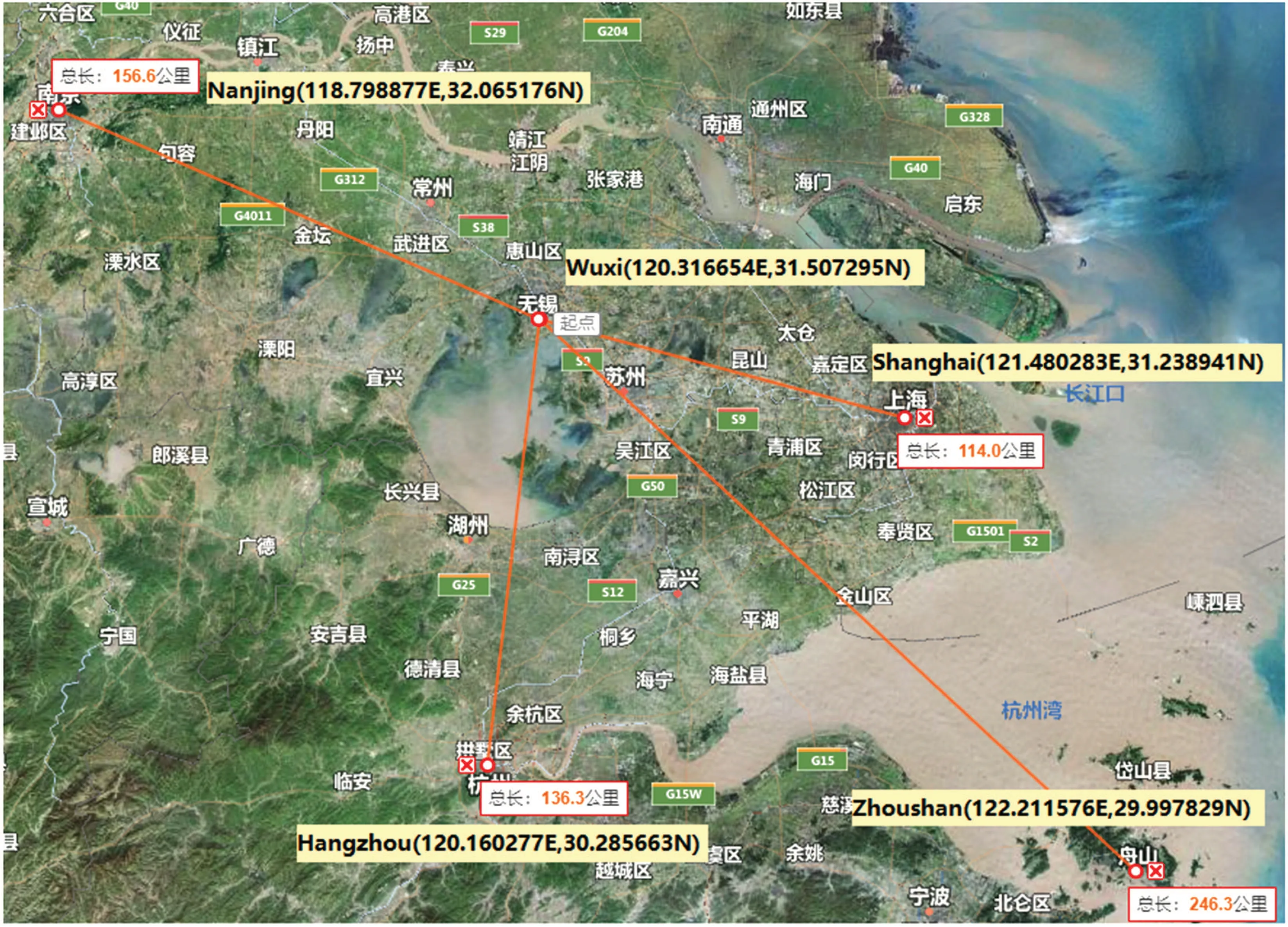
Fig.10.Overview of satellite map around Taihu lake.
Four path links from Wuxi (120.316654E, 31.507295N)to Hangzhou (120.160277E, 30.285663N), Nanjing(118.798877E, 32.065176N), Shanghai (121.480283E,31.238941N), and Zhoushan (122.211576E, 29.997829N)were selected and analyzed.
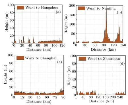
Fig.11.Two-dimensional section of the terrain from (a) Wuxi to Hangzhou, (b) Wuxi to Nanjing, (c) Wuxi to Shanghai, and (d) Wuxi to Zhoushan.
The two-dimensional section of terrain fluctuations on four path links are shown in Fig.11.The path link from Wuxi to Hangzhou is 120 km.It is routed to the boundary of Taihu Lake.There is a short distance of lake water cutoff, but the terrain is flat and there is no large undulation.Wuxi is far from Nanjing, separated by a distance of 150 km, and there are two high peaks reaching up to 200 m at 100 and 140 km.Wuxi is the closest to Shanghai, at a distance of 90 km, and the terrain is flat without much undulation.Finally, Wuxi is the furthest from Zhoushan.The terrain path is 270 km long and passes through Hangzhou Bay.It includes a water surface about 100 km long.
After the analysis, the two special terrains from Wuxi to Nanjing and Wuxi to Zhoushan were chosen to verify the new scattering parabolic equation model under the nonuniform surface.The two path links cover a long distance and contain relatively open and flat parts of the plain area.In addition,since the two path links also contain high mountain areas and lake water areas,they are highly representative.
4.2.Verification of new scattering parabolic equation on nonuniform surface
The two-dimensional topography,from Wuxi to Nanjing and Wuxi to Zhoushan, are shown in Figs.11(b) and 11(d),respectively.The new scattering parabolic equation algorithm proposed in this paper was used to calculate the spatial loss distribution of the two path links in evaporation ducts and surface ducts,considering the turbulence.The simulation results are compared with the results of the advanced refractive effects prediction system (AREPS).AREPS provides an end-to-end EM system propagation assessment tool.[33]The environmental inputs options of AREPS include tropospheric scattering,digital terrain,and atmosphere refractivity profile,etc.It is explored for military use at the beginning.Since Hitney’s RPO model was used in the original version of AREPS,comparison with results of AREPS to verify the new scattering PE model could be reasonable.The version of AREPS we used is version 3.6.In an actual mobile communication environment,the signal propagated by the horizontally polarized antenna generates a polarization current on the ground surface when it is close to the ground.The polarization current attenuated rapidly with the thermal energy generated by ground impedance.By using the signal propagated by vertical polarization antenna, it is not easy to generate a polarization current, which avoids the large attenuation of energy and ensures effective propagation of the signal.After calculation, the propagation loss in horizontal polarization mode was higher than the loss in vertical polarization, but the difference between the two was small.To reduce the number of base station antennas, the existing new technology was developed a ±45°polarization method with orthogonal vertical and horizontal polarizations.The performance of this dual-polarization mode is better,and the polarization diversity gain is about 2 dB higher than that of the single-polarized antenna.[34,35]Since we evaluated the existence of CCI caused by over-the-horizon propagation,horizontal polarization was chosen for the simulation.If CCI still exists under higher loss circumstance caused by the horizontal polarization mode,the interference source location and the interference prevention for the link will be necessary.
The simulation parameters in circumstance of evaporation duct are listed in Table 1.The 2 GHz of frequency in fourth-generation mobile networks was used.The surface electromagnetic constant was set as εr=40, σ =0.085 for vegetation area, εr=81, σ =0.22 for freshwater area, and εr=40,σ =0.001 for bare soil area.

Table 1.Simulation parameters in an evaporation duct.
Figures 12 and 13 show the spatial distributions of propagation loss calculated by the new scattering parabolic equation model and AREPS when there is evaporation duct on the two path links from Wuxi to Nanjing and Wuxi to Zhoushan.
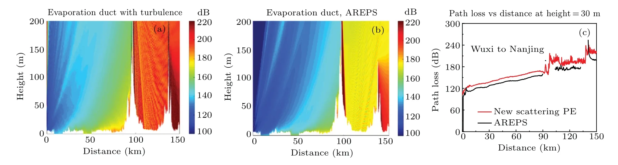
Fig.12.(a) Spatial propagation loss calculated by new scattering parabolic equation model, (b) spatial propagation loss calculated by AREPS, (c)difference of path loss vs.distance distribution at height of 30 m under two calculation methods in the evaporation duct on Wuxi–Nanjing link.
The new scattering parabolic equation fully considers the influence of turbulence factors and terrain fluctuations.The propagation loss vs.distance for a height of 30 m was obtained.It can be seen that calculation results of the new scattering PE model and that of AREPS are consistent in tendency.Since the source code of AREPS is unacquirable, and along with the update of the version of AREPS, the algorithm conducted by the application could be more precisely improved,and small difference on the results could exist.More improvement targeting the real climate or terrain could be done on the basis of the new scattering PE model.It is more operable comparing with AREPS.The applicability of the model under complex terrain factors is verified.
The minimum receiver signal level is assumed to be?160 dBW,which referenced from the configuration of GPS L2 receiver.If path loss is under 160 dB when signal arrived at another city,the long distance propagation form.Then there is probability that CCI between these two cities could happen.
From Fig.12(c), it can be seen that before 90 km, the terrain did not fluctuate too sharply, and the turbulence effect effectively reduced the propagation loss.At around 90 km and 135 km on the path link, owing to the existence of peaks up to 200 m,the propagation loss suddenly increased,that is,the radio wave was completely cut off by the mountain, and it was difficult to bypass the mountain to form a super horizontal propagation.Because of the topographical factor, the path link does not generate long-distance CCI.According to Fig.13(c), the terrain of Wuxi–Zhoushan path is relatively stable because of the topography,and the turbulence effect reduces part of the propagation loss.However, the propagation loss reached 180 dB at around 150 km.Therefore,in the case of the evaporation duct, CCI does not happen on the Wuxi–Zhoushan route.
The simulation parameters for the surface-based duct are listed in Table 2.
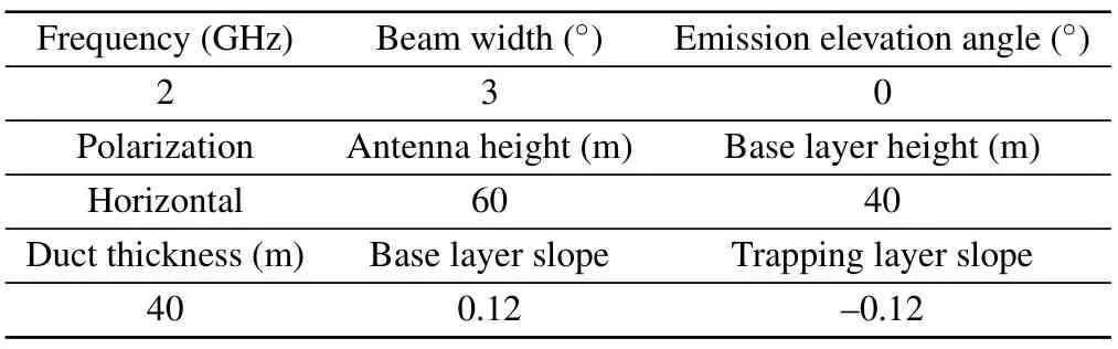
Table 2.Simulation parameters for the surface-based duct.
Figures 14 and 15 show the spatial distributions of the propagation loss calculated by the new scattering parabolic equation model and AREPS when there is a surface-based duct on Wuxi–Nanjing and Wuxi–Zhoushan links.In the case of a strong surface duct, both results are relatively consistent before the abrupt change in topography, and the applicability of the model in the case of the mountain peak, water path,and surface-based duct was validated.Figure 12 shows that the propagation loss of the Wuxi–Nanjing path is reduced,but clear truncation is observed at the two peaks.Hence, in the case of the surface duct, the link cannot form a long-distance CCI.
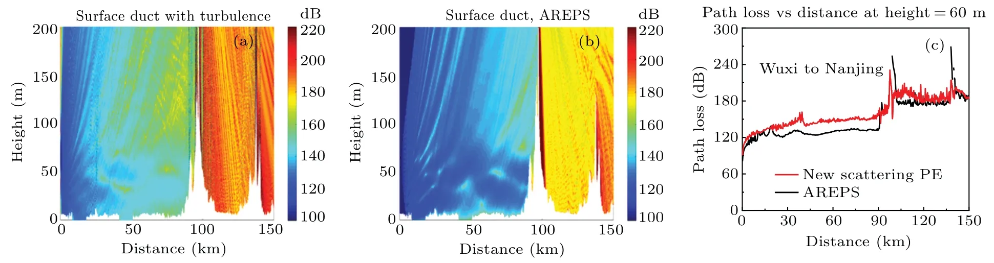
Fig.14.(a) Spatial propagation loss calculated by the new scattering parabolic equation model, (b) spatial propagation loss calculated by AREPS, (c) difference of path loss vs.distance distribution at height of 60 m under two calculation methods in the surface-based duct on Wuxi–Nanjing link.
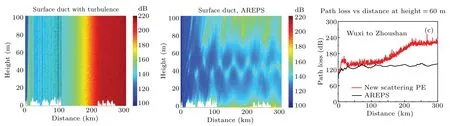
Fig.15.(a) Spatial propagation loss calculated by the new scattering parabolic equation model, (b) spatial propagation loss calculated by AREPS, (c) difference of path loss vs.distance distribution at height of 60 m under two calculation methods in the surface-based duct on Wuxi–Zhoushan link.
As shown in Fig.15, in the case of the surface duct,there is no terrain fluctuation at 110–210 km on the Wuxi–Zhoushan link.According to the map, the section passes through Hangzhou Bay.The sudden changes in the topographical factors led to an increase in propagation loss, but there were no high mountain peaks to block the propagation.Because of the strong surface duct effect and the turbulence effect, the signal loss was still about 150 dB when it reached Zhoushan area,beyond 300 km.That is,when a surface duct with strong duct strength was formed under certain weather conditions,the Wuxi–Zhoushan link may experience CCI.
4.3.CCI analysis of four path links under different meteorological conditions
We use the new scattering parabolic equation model to calculate the distribution of spatial propagation loss and propagation loss vs.distance at a certain height on the four path links in evaporation duct and the nonuniform turbulent environment under the fourth generation mobile networks,2 GHz.Other parameters were the same as those mentioned in the previous section.
Figure 16 shows the spatial distribution of the propagation loss in the evaporation duct on the four path links calculated by the new propagation model.Figure 17 shows a comparison of the propagation loss in the evaporation duct on different urban paths at a height of 30 m above the ground.
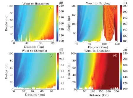
Fig.16.Spatial distribution of propagation loss of the fourth generation mobile networks in evaporation duct and turbulent medium from(a)Wuxi to Hangzhou,(b)Wuxi to Nanjing,(c)Wuxi to Shanghai,and(d)Wuxi to Zhoushan.
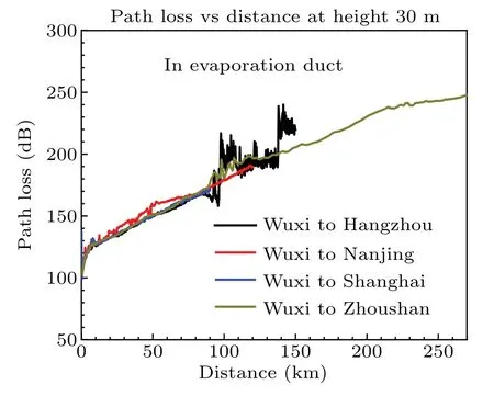
Fig.17.Comparison of propagation loss vs.distance at a height of 30 m on different urban paths.
According to the simulation results, under the environment of an evaporation duct and a turbulent medium,the overthe-horizon propagation effect is weak.Despite the close distance and the flat terrain of Wuxi–Shanghai link, the loss at 90 km is as high as 160 dB.When the minimum receiving loss sensitivity of the receiver is 160 dB,among the four path links,the CCI problem may occur only in Wuxi–Shanghai link.In other path links, owing to the switching of the propagation medium between land and water surfaces, the truncation of the mountain peaks or the long-distance of propagation,there is no hidden risk of CCI despite a strong evaporation duct.
The new scattering parabolic equation model was used to calculate the distribution of spatial propagation loss and propagation loss vs.distance at a certain height on the four path links in a surface-based duct and nonuniform turbulent environment under the same parameter settings as described in earlier sections.The spatial distribution of the propagation losses in the surface-based duct on the four path links calculated by the new propagation model are shown in Fig.18.
Figure 19 shows the comparison of propagation losses in a surface-based duct on different urban paths at a height of 60 m above the ground.Compared with the evaporation duct,the surface duct has stronger intensity, thereby significantly enhances the over-the-horizon propagation effect.The new scattering parabolic equation model considers the relationship between the turbulence effect and the height of the base layer and the thickness of the trap layer of surface duct.It also simulates the influence of turbulence on the over-the-horizon propagation better.
According to the propagation loss distribution of the communication signal at a height of 60 m on Wuxi–Nanjing link,except for the presence of two peaks up to 200 m high(which intercept the propagating signal),CCI may occur on the other three path links in the surface-based duct.In the Wuxi–Hangzhou link, which passes through Taihu Lake, there are several sections of land and water boundary switching, and hence, the path loss fluctuates greatly.The Wuxi–Shanghai link experiences no significant changes in propagation loss because of the flat terrain.The distance from Wuxi to Zhoushan across Hangzhou Bay is longer.In addition to a certain mutation in the border area, path loss on water surface is small,and Hangzhou Bay has no significant impact on the over-thehorizon propagation between the two cities.In addition, according to the satellite map shown in Fig.10, within 90 km from Wuxi,except for the Taihu area on the Wuxi–Hangzhou link, the first 90 km of the other three links of the Wuxi–Nanjing, Wuxi–Zhoushan, and Wuxi–Shanghai are similar in topography and geomorphology,and there are no large undulations in the plain area.Therefore, under the identical duct and turbulence settings,the path loss in the distance direction has little difference.
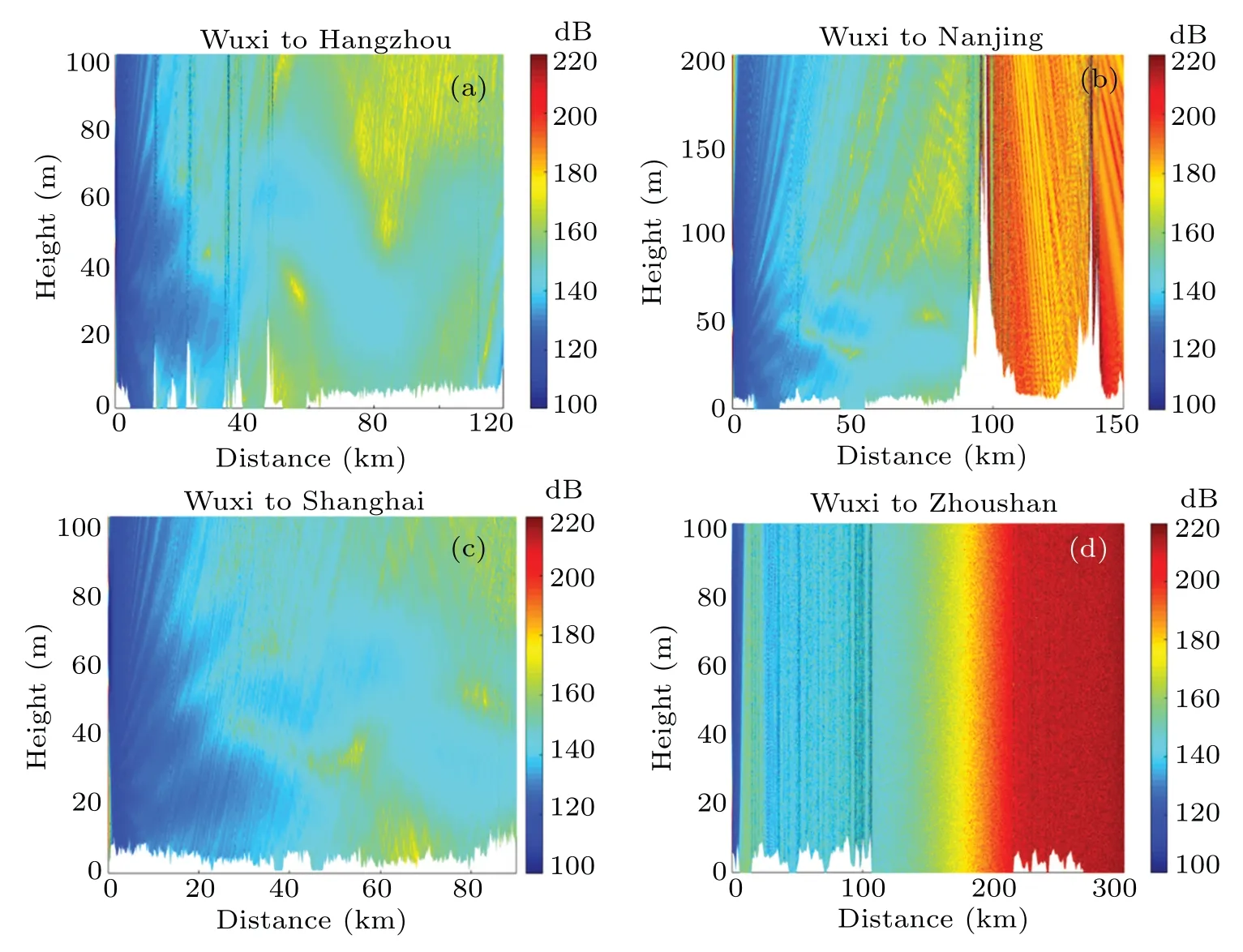
Fig.18.Spatial distribution of propagation loss of the fourth generation mobile networks in the surface-based duct and turbulent medium from(a)Wuxi to Hangzhou,(b)Wuxi to Nanjing,(c)Wuxi to Shanghai,and(d)Wuxi to Zhoushan.
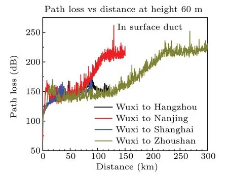
Fig.19.Comparison of propagation loss vs.distance at a height of 60 m on different urban paths.
5.Discussion
By calculating the over-the-horizon propagation loss at the frequency of the fourth-generation mobile communication signal caused by the duct effect and turbulence effect, which occur on the four path links Wuxi–Nanjing, Wuxi–Shanghai,Wuxi–Zhoushan, and Wuxi–Hangzhou, whether CCI occurs on the four path links under the condition of analog receiver sensitivity, is analyzed.In terms of duct strength, the surface duct is stronger than the evaporation duct,and the electromagnetic wave signal propagates farther with less loss in the surface duct environment.With regard to the coupling of the top layer of the surface duct and turbulence, a new nonuniform turbulence mode is used to simulate the combined effect of the actual surface duct and turbulence effect better.However,statistics show that, in fact, an evaporation duct has a higher probability of occurrence than that of a surface duct.Although the duct strength is not stronger than that in the latter,the CCI in the evaporation duct environment is more frequent, so the simulation results in evaporation duct and turbulence environment are more practical.In addition, the analysis shows that flat terrain has little effect on propagation loss, except in the case of a sudden change in the topographical medium such as the alternation between water and land media or a prominent mountain blockage.Therefore,if there is no abrupt terrain between the propagation links,only the ducts and turbulence will have a great influence on CCI.In this work,CCI propagation in the east of China plain was studied.The model is also applicable to similar terrains in other countries.Evaporation ducts and surface ducts occur mostly in the plains and near the water bodies after a rain.CCI can easily occur between cities with flat terrains when ducting and turbulence exist.
6.Analysis of long-distance CCI in 5G area
The 5G mobile communication technology will support a greater bandwidth,more connections and lower latency.From the perspective of the key technology of the entire physical layer, the main innovation of 5G commercial technology is the introduction of massive multiple input multiple output (MIMO) technology, which can improve the effectiveness and reliability of communication.In the enhanced largebandwidth scenario of enhanced mobile broadband (eMBB)deployment,the massive MIMO base station(MMBS)plays a key role.
With the official launch of 5G mobile phone mobile data packages by the three major operators in China,most cities in China have begun large-scale deployment of base stations for 5G mobile communications.Owing to the special TDD characteristics of the TD-LTE system, a certain GP cannot completely avoid long-distance CCI.In the rural areas of the central China plain and certain coastal areas, when atmospheric ducts are formed under certain weather conditions, the longdistance CCI between the base stations of the TD-LTE system is bound to intensify.This problem is difficult to eliminate fundamentally through the conventional network structure adjustments.The optimization algorithm can be used to determine the type of atmospheric duct interference,and then,the atmospheric duct interference can be suppressed algorithmically to stabilize the network indicators.Alternatively,one can locate the interference source when the long-distance CCI occurs and improve base station networks and systems sequentially.
The 5G signals would be millimeter wave.Different frequency bands cause different propagation loss in ducting and tropospheric turbulence.The receiver minimum level would change as well.More intensive networking systems are needed.The new scattering PE model could be used to evaluate the probability of CCI between cities or long distance links before the base stations are located, or the frequency bands could be allocated as sparingly as possible considering the simulation results.
7.Conclusion
In the 5th generation mobile networks of the future,higher communication frequency bands will be accompanied by greater tropospheric scattering effects and more serious over-the-horizon propagation.The over-the-horizon propagation of the corresponding 5th generation mobile networks may cause CCI and affect the information security of information propagation.In the eastern part of China, which has areas with plains and open areas, the increase in temperature after a heavy rain is likely to form an atmospheric duct.When the signal propagates through the trapping layer of the duct,it can travel farther through the turbulent scattering at the top of the duct layer with a low propagation loss.In cities in the plains,there is a high probability of occurrence of CCI.
In this paper,a new scattering parabolic equation model is proposed.This model is suitable for calculating the effects of CCI caused by over-the-horizon propagation between different urban surfaces in turbulent media when an evaporation duct or a surface duct forms.The over-the-horizon communication between four city links,namely Wuxi–Hangzhou,Wuxi–Nanjing,Wuxi–Shanghai and Wuxi–Zhoushan were analyzed.The possibility of CCI was evaluated based on the propagation loss calculated by the model on the corresponding link.We concluded that both the ducting effect and the turbulence effect may enhance the over-the-horizon propagation,thereby reduce the path loss and causing CCI.In addition,in the presence of towering mountains or islands on the path, on reaching the duct trap height,signal propagation may be affected.If the obstacle is sufficiently high,the signal may be completely blocked.An abrupt change in the boundary medium under the propagation of land and water affects propagation,but a longer land surface and water surface interface have little effect on the over-the-horizon propagation and CCI.In this work, only CCI caused by over-the-horizon propagation of complex terrain between cities was evaluated.However, elimination of this phenomenon requires further study.
Acknowledgements
Project supported by the National Natural Science Foundation of China (Grant Nos.62005205, 62071359, and 61775175) and Natural Science Basic Research Program of Shaanxi,China(Grant No.2020JQ-331).
- Chinese Physics B的其它文章
- High sensitivity plasmonic temperature sensor based on a side-polished photonic crystal fiber
- Digital synthesis of programmable photonic integrated circuits
- Non-Rayleigh photon statistics of superbunching pseudothermal light
- Refractive index sensing of double Fano resonance excited by nano-cube array coupled with multilayer all-dielectric film
- A novel polarization converter based on the band-stop frequency selective surface
- Effects of pulse energy ratios on plasma characteristics of dual-pulse fiber-optic laser-induced breakdown spectroscopy