
Motion synchronization in a dual redundant HA/EHA system by using a hybrid integrated intelligent control design
2016-11-23 06:13WaheedUrRehmanWangShaopingWangXingjianFanLeiKamranAliShah
CHINESE JOURNAL OF AERONAUTICS 2016年3期
Waheed Ur Rehman,Wang Shaoping,Wang Xingjian,Fan Lei,Kamran Ali Shah
School of Automation Science and Electrical Engineering,Beihang University,Beijing 100191,China
Motion synchronization in a dual redundant HA/EHA system by using a hybrid integrated intelligent control design
Waheed Ur Rehman,Wang Shaoping,Wang Xingjian*,Fan Lei,Kamran Ali Shah
School of Automation Science and Electrical Engineering,Beihang University,Beijing 100191,China
This paper presents an integrated fuzzy controller design approach to synchronize a dissimilar redundant actuation system of a hydraulic actuator(HA)and an electro-hydrostatic actuator(EHA)with system uncertainties and disturbances.The motion synchronous control system consists of a trajectory generator,an individual position controller for each actuator,and a fuzzy force tracking controller(FFTC)for both actuators.The trajectory generator provides the desired motion dynamics and designing parameters of the trajectory which are taken according to the dynamic characteristics of the EHA.The position controller consists of a feed-forward controller and a fuzzy position tracking controller(FPTC)and acts as a decoupled controller,improving position tracking performance with the help of the feed-forward controller and the FPTC.The FFTC acts as a coupled controller and takes into account the inherent coupling effect.The simulation results show that the proposed controller not only eliminates initial force fighting by synchronizing the two actuators,but also improves disturbance rejection performance.
1.Introduction
The reliability requirements of large aircraft are increasingly high,so conventional flight control systems adopt similarredundant hydraulic actuators with central hydraulic power supply systems.Hydraulic actuators(HAs)have very good characteristics such as small size-to-power ratio and ability to provide large torque and force.1–3However,this configuration is difficult to further enhance aircraft reliability because of their heavy reservoirs,long pipes,and other necessary accessories.In order to improve aircraft reliability and maintainability, A380 firstly develops a dissimilar redundant actuation configuration based on an HA and an electrohydrostatic actuator(EHA).4Since the EHA is a distributed electro-hydrostatic actuation system,in which an electrical motor acts as the control unit and a hydraulic pump works as the transmission part,its dynamic performance is totally different from that of the HA.5The EHA takes advantage of electric technology,including environmental cleanliness,energy saving,and reduced hydraulic pipes.6–8Therefore,in the dissimilar redundant actuation system,the HA/EHA is the best option for an application that needs high force and requires high fault tolerance capability.9–11
Although the dissimilar redundant actuation system not only reduces weights but also improves maintainability with segregating power distribution channels,its control faces a challenge because of the different dynamic performances between the HA and the EHA.12
There are two operating modes for the dissimilar redundant actuation system,i.e.,HA active/EHA active(A/A)mode and HA active/EHA passive(A/P)mode.13Most aircraft use the A/P mode,but there are certain circumstances,such as sudden storms or actuator failure,that demand the A/A mode.14The HA and the EHA are connected to the control surface through a rigid connection,in which these two actuators have different driving principles.The coupling effect that is due to the rigid connection between them produces force fighting.Force fighting is the amount of force difference between the HA and the EHA,which not only disturbs tracking accuracy,but also can damage the control surface.15Therefore,how to control force fighting by taking the inherent coupling effect into account is a hot topic for modern aircraft.
In order to check and analyze the performance of the dissimilar redundant actuation system,a test bench of the hybrid system has been built by GOODRICH Company and INSA University.13,16Two strategies have been given.One strategy uses an active mode without load,in which the actuator position difference,velocity difference,and force difference are used by a position controller to synchronize them.The other strategy uses a multiple-input multiple-output(MIMO)control method based on a state observer to reduce force fighting.17The difference between the average actuator force and the actual actuator force is given to the integrator to generate a position demand offset for eliminating force fighting.10Different techniques for static force equalization and dynamic force equalization have been studied,10,15,18but there is a flaw in the above techniques because they seldom consider their coupling effect.In fact,it is the mutual coupling between the HA and the EHA that is the key to restrict its dynamic performance.
In order to improve the tracking performance of the hybrid system,the coupling effect should be taken into account.Motion synchronization can guarantee the elimination of force fighting.With the purpose of reducing the force fighting effect between different channels,a robust adaptive fuzzy method that takes the coupling term through T–S fuzzy is proposed for a multi-input and multi-output system.19,20An adaptive fuzzy sliding mode controller is designed for a two-joint manipulator and every joint can realize high precision tracking control by using fuzzy terminal sliding mode control.21Robust control theory is used to solve the coupling problem by taking coupling as disturbance between different channels and a synchronous controller is designed with the help of quantized field theory(QFT).22,23An adaptive PID controller is used for speed control of a permanent magnetic synchronous motor.24,25
However,the above literatures only focus on the coupling effect and not investigating the source of coupling between the HA and the EHA.In addition,the controller design doesn't consider the system uncertainties and disturbances.This paper presents an integrated fuzzy controller based on a trajectory generator,a piston controller,and a fuzzy force tracking controller(FFTC).The trajectory generator provides the desired motion dynamics(position,velocity,acceleration)and the designing parameters of the trajectory are taken according to the dynamic characteristics of the EHA.The position controller consists of a feed-forward controller and a fuzzy position tracking controller(FPTC)and acts as a decoupled controller,improving position tracking performance with the help of the feed-forward controller and the FPTC.The FFTC acts as a coupled controller and takes into account the inherent coupling effect to synchronize two actuators and improve disturbance rejection performance.Through trajectory control,position decoupling control,and force tracking control,the dissimilar redundant actuation system can approach desired dynamics,reduce the position tracking error caused by disturbances and nonlinearities,and improve the load rejection performance through taking into account the inherent coupling effect between the HA and the EHA.The simulation results illustrate that the proposed controller is effective to eliminate initial force fighting and to improve disturbance rejection performance.
2.Mathematical modeling of the dissimilar redundant actuation system
The structure of the dissimilar redundant actuation system is shown in Fig.1,which consists of an EHA(combination of a motor,a pump,and a hydraulic cylinder),an HA(combination of a servo valve and a hydraulic cylinder),and a control surface.The pilot gives the command to a flight control computer which drives the servo valve of the HA and the motor of the EHA respectively.
In Fig.1,Fhand Feare the output forces of the HA and the EHA,respectively,while FLis an equivalent air load force.
Since some nonlinear factors exist in the HA and the EHA,the dynamic performance of the HA is different from that of the EHA.In addition,the disturbance around the dissimilar actuation system will also influence the dynamic performances of the HA and the EHA.Therefore,there are some differences between the HA and the EHA,leading to the force fighting act on the control surface.If the force fighting acts on the surface continuously,it may result in damage of the control surface.Therefore,it is necessary to figure out the reasons of the force fighting and find a solution to eliminate the force fighting effectively for satisfying maneuvering performance.In order to analyze the dynamic performance of the whole system,it needs to drive mathematical models of the HA,the EHA,and the control surface.
2.1.Mathematical models of the actuators
2.1.1.HA modeling
The HA includes a hydraulic power supply system,a servo valve,a cylinder,and a displacement sensor,as shown in Fig.1.The mathematical model of the HA is derived according to the displacement and load flow of the servo valve.In order to derive a mathematical model of the HA,the nonlinearities are ignored.Suppose that the spool displacement of the servo valve is linearly related to the servo valve current and the flow of the servo valve is linear around null opening to the servo valve current and load pressure as follows:
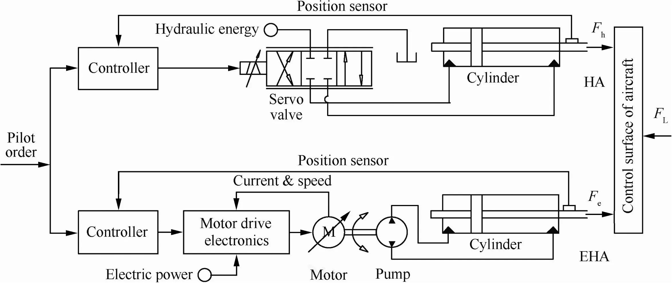
Fig.1 Structure of the dissimilar redundant actuation system.

where xvis the spool displacement of the servo valve;Kiis the opening/current gain of the servo valve;Isis the input current of the servo valve;Qhis the flow of the servo valve;Kqis the flow/opening gain at null pressure drop of the servo valve;Kcis the servo valve flow/pressure gain;Phis the load pressure of the servo valve.
The flow dynamics and force dynamics of the cylinder can be described by:

where Ahis the piston area;xhis the displacement of the cylinder;Vhis the total volume of the cylinder;Ehis the effective bulk modulus;mhis the mass of the hydraulic cylinder rod;Bhis the viscous resistance in the hydraulic cylinder;Chlis the leakage coefficient.
Combine Eqs.(1)and(2)to obtain the block diagram of the HA shown in Fig.2,in which Kce=Chl+Kcis the total leakage coefficient.
2.1.2.EHA modeling
The EHA consists of a motor,a hydraulic pump,a cylinder,a displacement sensor,and a control surface,as shown in Fig.1.In order to derive a mathematical model of the EHA,the nonlinearities are ignored.The dynamics of the pump controlled motor in the form of voltage balance,torque balance,and load torque equation are given as


Fig.2 Block diagram of the HA.
where Ueis the applied voltage inputting to the EHA;Keis the back-EMF constant;ωeis the angular velocity;Leis the armature inductance;Reis the armature resistance;ieis the motor current;Kmis the electromagnetic torque constant;Jmis the inertia of the rotor and the shaft;Bmis the total damping between the motor and the shaft;Te=VpPeis the load torque on the shaft,in which Vp=V/2π,where V is the pump displacement,and Peis the load pressure.
For the hydraulic cylinder of the EHA,the flow dynamics and force dynamics can be described by:

where Qe=Vpωeis the output flow of the pump;Aeis the effective area of the hydraulic cylinder piston;xeis the output displacement of the EHA;Veis the total volume of the hydraulic cylinder;Eeis the effective bulk modulus;Celis the total leakage factor;meis the mass of the hydraulic cylinder rod;Beis the viscous resistance in the hydraulic cylinder.
Let Bme=KeKm/Re+Bmand combine Eqs.(3)and(4)to obtain the block diagram of the EHA as shown in Fig.3,where the armature inductance is ignored because of its very small value compared with that of the armature resistance.
2.2.Mathematical model of the control surface
Suppose that the actuators are rigidly connected to the control surface and the movement angle θdof the control surface is not large and equal to the linear movement xdof the control surface,i.e.,θd=xd/rd,where rdis the radial distance of the control surface.The structure of the control surface driven by the hydraulic cylinder is shown in Fig.4.
The force dynamics of the aircraft control surface can be given as

where K is the transmission stiffness;mdis the mass of the control surface;Bdis the viscous damping coefficient;Kdis the aero elasticity.Fhand Fecan be described by:

2.3.Force fighting analysis
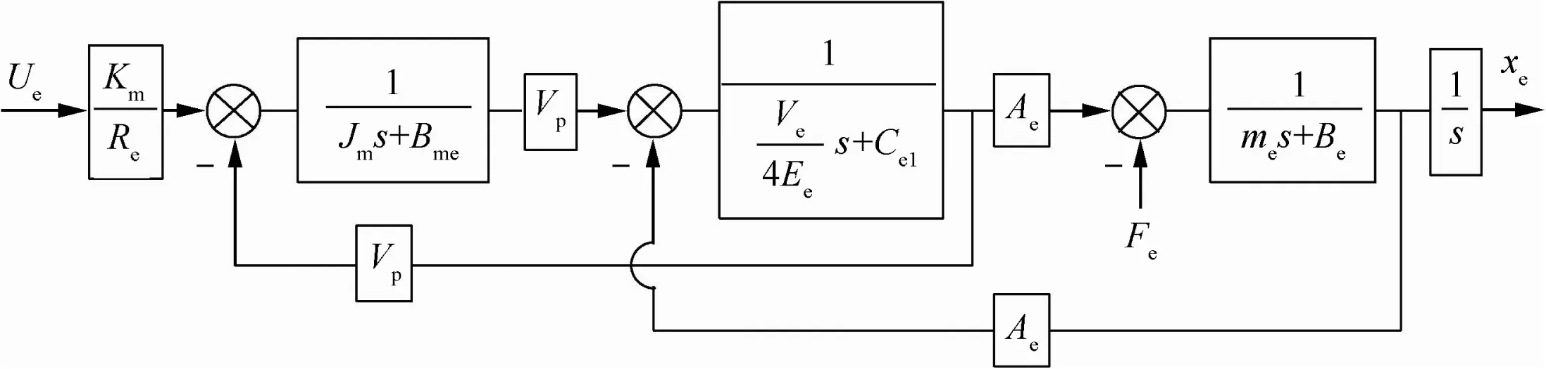
Fig.3 Block diagram of the EHA.

Fig.4 Driving mechanism of the control surface.
Due to different stiffness properties,tolerances,and components,the force fighting on the shaft exists between the HA and the EHA in the dissimilar redundant actuation system.The dynamic force fighting is a very important issue that influences the dynamic performance of the actuation system.The force fighting can decrease the system efficiency and cause surface damage.In order to remove the dynamic force fighting,it is required that the HA and the EHA should have identical pursuit dynamics and rejection properties.
Fig.5 shows the connection of the dissimilar redundant actuation system based on the HA and the EHA with an external load force FL,in which the HA possesses a displacement xhand a load force Fhand the EHA has a displacement xeand a load force Feunder the same input.Xris the reference input of the system.
The transfer function of the HA displacement is given by

where G1(s)is the input transfer function of the HA and G2(s)is the disturbance rejection function of the HA.
The transfer function of the EHA displacement is given by

where H1(s)is the input transfer function of the EHA and H2(s)is the disturbance rejection function of the EHA.
The force fighting efis defined as the force difference between the two actuators,and given by

Eq.(9)shows that the force fighting will be zero under two conditions:(1)when 1/G1(s)and 1/H1(s)are the same(the position pursuits functions are the same);(2) when G2(s)/G1(s)and H2(s)/H1(s)are the same(the rejection functions of the actuators to external force are the same).

Fig.5 Diagram of the dissimilar redundant actuation system.
3.Hybrid integrated intelligent control design for motion synchronization
For the dissimilar redundant actuation system,it is difficult to design a controller that can get the desired performance for the HA and the EHA due to inconsistent dynamics between the HA and the EHA.Hence,this paper presents an intelligent nested fuzzy controller shown in Fig.6,which consists of a trajectory generator,a position controller,and an FFTC to improve load rejection performance.
3.1.Trajectory generator
The desired dynamics are set by the trajectory generator.Trajectory generates three outputs as the reference position Xtr,velocityand accelerationby taking Xras the reference input.The trajectory which is going to be used in this research is a second-order transfer function;it has two designing parameters,the reference frequency ωiand the reference damping factor ?ishown in Fig.7.These two parameters of the EHA are used in building the desired trajectory.
3.2.Position controller
The position controller for the actuators consists of a feedforward controller and an FPTC,as shown in Fig.8.
In Fig.8,Is1and Ue1are the outputs of the feed-forward controller for the HA and the EHA,respectively,while similarly Is2and Ue2are the outputs of the FPTC for the HA and the EHA,respectively.The feed-forward controller overcomes sluggish dynamics and acts in a pre-defined way while the FPTC ensures the system operate in a desired point and improves performance robustly.The position controller uses a feedback controller and a feed-forward controller together to provide a rapid response and to track the desired motion given by the trajectory generator.
3.2.1.Feed-forward controller
It is a control technique that responds to disturbance in a predefined way.A feed-forward controller is based on prediction of plant behavior and can react before an error occurs.Therefore,it overcomes sluggish dynamics and delays in the system and also doesn't influence system stability.It has the disadvan-tage that it acts against disturbance by prediction,not by measuring disturbance,so it will not be accurate enough if the system changes.A feed-forward controller ideally consists of an exact inverse model of a plant,so it can compensate for known plant dynamics,delays,and errors before they happen.

Fig.6 Controller structure for the dissimilar redundant actuation system.

Fig.7 Schematic of second order trajectory.

Fig.8 Structure of the position controller.
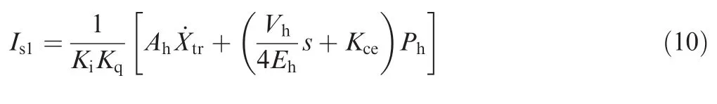
Based on the actuator model,the feed-forward controller algorithm implements the equivalent inverse dynamics by assuming that the actuator output is the desired reference trajectory.Taking the HA as an example and considering the mathematical model of the HA(i.e.,Eqs.(1)and(2)),the feed-forward controller for the HA can be designed as:
3.2.2.Fuzzy position tracking controller
In order to further improve position tracking control performance and to compensate for inaccuracies caused by disturbances and nonlinearities,the FPTC is designed for each individual actuator.
The conventional PI controllers have been widely used in many applications for industrial automation and process control because of simplicity and ease of operation.Fuzzy control is a very good approach for some systems such as higher-order nonlinear systems,time-delay linear systems,and complex systems that have no precise and accurate models.26,27Considering the difficulties to get a highly precise mathematical model of the HA/EHA redundant actuation system and high position tracking performance,a hybrid fuzzy PI control approach as the FPTC is used in this paper.The structure of the fuzzy position tracking controller is shown in Fig.9.It is just like a parallel combination in which fuzzy logic is used to tune the parameters of a PI controller.
In Fig.9,epis the position tracking error.Dp1and Dp2are the gains to convert the input(position tracking error)into a form which is suitable for interfacing of the fuzzy logic controller.C1,C2,G2,and G2are the controller parameters needed to be adjusted.andare the turning parameters.
The fuzzy logic controller may be considered as a parallel combination in which fuzzy logic is used to tune the parameters of a PI controller,and it has four main components:
(1)The''rule basequot;holds the knowledge,in the form of a set of rules as shown in Table 1,and every rule represents the states of member functions which are shown in Table 2.
(2)The inference mechanism evaluates control rules and makes a decision.
(3)The fuzzification interface simply modifies the input into such a form that can be easily interpreted and compared to the rules.
(4)The defuzzification interface converts the conclusions given by the inference mechanism to the plant.
The triangular member function μrwill be used whose general formula is given as

Fig.9 Structure of the fuzzy position tracking controller.

Table 1 Fuzzy rules for the FPTC.

where r∈{NB,NS,ZE,PS,PB,S,MS,M,MB,B}.
The fuzzy rules for all tuning parameters of the FPTC is the same but their membership functions are different.The membership function for each parameter of the FPTC is given in Table 2.
Suppose that the varied ranges of parameters Kpand Kiof the FPTC are bounded.A suitable range of each parameter can be found by the simulation of the convention PI controller.The range of each parameter for the FPTC of the HA is Kp∈[0.82,0.88]and Ki∈[5.20,5.50].The range of each parameter for the FPTC of the EHA is Kp∈[8950,9050]and Ki∈[21,900,22,100].They can be calibrated by using a general formula given by

where subscript z shows the type of the tuning parameter,and it may be proportional or integral.
3.3.Fuzzy force tracking controller
The position controller is designed to improve position tracking performance of each individual actuator.However,it does not take into account the inherent coupling effect in a hybrid redundant actuation system of HA/EHA,so the position controller can't improve load rejection performance effectively.Motion synchronization and position tracking performance are equally important in the dissimilar redundant actuation system.To address motion synchronization,an FFTC is proposed to connect two individual actuators and to synchronize motion between the HA and the EHA.The FFTC is basically a PID-type hybrid fuzzy control algorithm as shown in Fig.10.
In Fig.10,Df1and Df2are the gains to convert the input(force tracking error)into a form which is suitable for interfacing of the fuzzy logic controller.andare the turning parameters.Kph,Kih,Kdh,Kpe,Kie,and Kdeare the PID controller parameters.Is3and Ue3are the outputs of the fuzzy force tracking controller for the HA and the EHA,respectively,and can be determined from the fuzzy rules presented in Table 3.
The membership function for each parameter of the FFTC is given in Table 4.
The varied ranges of the parameters of the FFTC are bounded.A suitable range of each parameter was found by experiments.The range of each parameter for the FFTC is Kph∈[4.7X10-6,4.9X10-6], Kih∈[1.18X10-6,1.2X10-6],Kdh∈[1.9X10-7,2.1X10-7], Kpe∈[0.097,0.099], Kie∈[1.98X10-6,2X10-6],and Kde∈[8.98X10-3,9X10-3].Eq.(12)is also used as the parameter adjustment mechanism for the FFTC.
Furthermore,there are two low pass filters at the output of the FFTC used to remove the noise in the signal.For Is3,it is found that the noises are signals with a high frequency(20 Hz),while for Ue3,it is found that the noises are signals with afrequency above 79 Hz.Therefore,the gain of the low pass filter is Kf=1.The transfer function of the low pass filter is given by

Table 2 Membership functions for the FPTC.

Fig.10 Internal structure of fuzzy force tracking controller.

Table 3 Fuzzy rules for the FFTC.
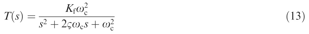
where ωcis the cut-off frequency;Kfis the passband or gain of the filter;? is the damping factor.
4.Simulation results and discussion
In order to verify the effectiveness of the proposed controller,this paper applies the control strategies of pursuit,rejection,and force equalization into MATLAB/Simulink by using the parameters shown in Table 5.
4.1.Simulation results with a square wave load
In this simulation,a step demand(30 mm position signal)is sent at time 0 s with an external force of 15000 N.The external force is a square wave of a 2 s period with a 1 s phase delay and a 50%pulse width of the period and it acts on the surface from 1 s to 5 s.The simulation results are shown in Fig.11.
It is noted that the maximum force fighting for the PID design strategy is 8350 N initial and there is no external force at that time.The integrated fuzzy controller strategy has no initial force fighting.Then a 15 kN external load(force)acts on the control surface at a time of 1 s with a period of 2 s.It is observed that the force fighting for PID control is-6800 N,while the force fighting for the integrated fuzzy controller strategy is-1400 N at that time.It means that the proposed strategy has reduced 79.4%force fighting as compared to the PID strategy.Force fighting comparison of the proposed strategy with the PID strategy is given in Table 6.
Furthermore,it shows that the integrated fuzzy strategy has better synchronization.The proposed strategy also quickly follows the signal given by the desired trajectory as compared to the PID strategy as shown in Fig.11(b).In addition,for PID,the load pressures of the HA and the EHA have a greater difference as shown in Fig.11(c),which causes poor synchronization.The integrated fuzzy strategy has a less difference between the load pressures of the HA and the EHA as compared to the PID strategy as shown in Fig.11(d).
4.2.Simulation results with a sinusoidal wave load
Suppose that the control surface of the aircraft(at a time of 1 s)experiences a disturbance(load)just like a sine wave of 15 kN in amplitude and 2 s in period.The simulation results are shown in Fig.12.
It is noted that the maximum force fighting for the PID design strategy is 8350 N initial(at 0 s)and there is no external force at that time.The integrated fuzzy controller strategy has no initial force fighting.The force fighting when the external load acts on the control surface is-4430 N for the PID strategy and it is-400 N for the integrated fuzzy strategy.Comparison of force fighting is given in Table 7.
In this simulation,it also shows that the fuzzy integrated strategy has better synchronization then the PID strategy according to Fig.12(b).For PID,the load pressures of the HA and the EHA have a greater difference as shown inFig.12(c),which causes poor synchronization.Compared to the PID strategy,the integrated fuzzy strategy has a less difference between the load pressures of the HA and the EHA as shown in Fig.12(d).

Table 4 Membership functions for the FFTC.

Fig.11 Simulation results with a square wave load.

Fig.12 Simulation results with a sine wave load.
Robustness is a property that shows how much system performance is sensitive to uncertainties(disturbances,variations in parameters,etc.).The PID strategy is not robust because it doesn't count the coupling effect.However,the integratedfuzzy controller strategy is robust because it counts the coupling effect and consists of feedback and feed-forward controllers to make the system fast with reduced errors.

Table 5 Simulation parameters for the dissimilar redundant system.

Table 7 Comparison between strategies under a sine wave load.
5.Conclusions
In this paper,an integrated fuzzy controller design is proposed that consists of a trajectory generator,a position controller,and an FFTC.The trajectory generator is designed according to the dynamic characteristics of the EHA.The position controller combines the advantages of a feed-forward controller and a feedback controller to reduce force fighting and synchronize them by taking input signals from the trajectory generator.The FFTC improves load rejection performance and reduce dynamic force fighting by taking into account the inherent coupling effect.Simulation results show that the proposed controller design strategy completely removes initial force fighting,while there is a very big improvement in eliminating force fighting.It is also shown that the load pressure difference is also smaller as compared to that of PID and the proposed strategy has better tracking performance.
Acknowledgments
This work was supported by the National Basic Research Program of China(973 Program)(No.2014CB046402),the National Natural Science Foundation of China (Nos.51575019,51305011),and the 111 Program of China.
1.Ahn KK,Nam DNC,Jin M.Adaptive backstepping control of an electrohydraulic actuator.IEEE/ASME Trans Mechatron 2014;19(3):987–95.
2.Wang XJ,Wang SP.High performance adaptive control of mechanical servo system with lugre friction model:identification and compensation.J Dyn Syst Meas Contr 2012;134(1):011021.
3.Yao B,Bu F,Reedy J,Chiu GT.Adaptive robust motion control of single-rod hydraulic actuators:theory and experiments.IEEE/ASME Trans Mechatron 2000;5(1):79–91.
4.Goupil P.Airbus state of the art and practices on FDI and FTC in flight control system.Control Eng Pract 2011;19(6):524–39.
5.Kang RJ,Jiao ZX,Wang SP,Chen LS.Design and simulation of electro-hydrostatic actuator with a built-in power regulator.Chin J Aeronaut 2009;22(6):700–6.
6.Grabbel J,Ivantysynova M.An investigation of swash plate control concepts for displacement controlled actuators.Int J Fluid Power 2005;6(2):19–36.
7.Li K,Lv Z,Lu K,Yu P.Thermal-hydraulic modeling and simulation of the hydraulic system based on the elec-tro-hydrostatic actuator.Procedia Eng 2014;80:272–81.
8.Lin Y,Shi Y,Burton R.Modeling and robust discrete-time sliding-mode control design for a fluid power electrohydraulic actuator(EHA)system.IEEE/ASME Trans Mechatron 2013;18(1):1–10.
9.Tri NM,Nam DNC,Park HG,Ahn KK.Trajectory control of an electro hydraulic actuator using an iterative backstepping control scheme.Mechatronics 2014;29:96–102.
10.Shi C,Wang XJ,Wang SP,Wang J,Tomovic MM.Adaptive decoupling synchronous control of dissimilar redundant actuation system for large civil aircraft.Aerosp Sci Technol 2015;47:114–24.
11.Bauer C,Lagadec K,Bès C,Mongeau M.Flight control system architecture optimization for fly-by-wire air-liners.J Guid Control Dyn 2007;30(4):1023–9.
12.Rosero J,Ortega J,Aldabas E,Romeral L.Moving towards a more electric aircraft.IEEE Aerosp Electron Syst Mag 2007;22(3):3–9.
13.Yu LM,Ye ZQ.Research on performances of hybrid actuation system with dissimilar redundancies.Adv Mater Res 2012;430–432:1559–63.
14.Ismail S,Pashilkar AA,Ayyagari R,Sundararajan N.Improved neural-aided sliding mode controller for auto-landing under actuator failures and severe winds.Aerosp Sci Technol 2014;33(1):55–64.
15.Guo LL,Yu LM,Lu Y,Fan DL.Multi-mode switching control for HSA/EHA hybrid actuation system.Appl Mech Mater 2014;494–495:1088–93.
16.Karam W,Mare JC.Force control of a rollerscrew electromechanical actuator for dynamic loading of aerospace actuators.International conference on fluid power and motion control;2008.p.515–28.
17.Cochoy O,Hanke S,Carl UB.Concepts for position and load control for hybrid actuation in primary flight controls.Aerosp Sci Technol 2007;11(2):194–201.
18.Wang LJ,Mare′JC.A force equalization controller for active/active redundant actuation system involving servo-hydraulic and electro-mechanical technologies.Proc Inst Mech Eng Part G J Aerosp Eng 2014;228(10):1768–87.
19.Li TS,Tong SC,Feng G.A novel robust adaptive-fuzzy-tracking control for a class of nonlinear multi-input/multi-output systems.IEEE Trans Fuzzy Syst 2010;18(1):150–60.
20.Wang XJ,Wang SP,Zhao P.Adaptive fuzzy torque control of passive torque servo systems based on small gain theorem and input-to-state stability.Chin J Aeronaut 2012;25(6):906–16.
21.Li THS,Huang YC.Mimo adaptive fuzzy terminal sliding-mode controller for robotic manipulators.Inf Sci 2010;180(23):4641–60.
22.Wang XJ,Wang SP,Yao B.Adaptive robust torque control of electric load simulator with strong position coupling disturbance.Int J Control Autom Syst 2013;11(2):325–32.
23.Taher SA,Hematti R,Abdolalipour A,Nemati M.Decentralized controller design for static synchronous compensator using robust quantitative feedback theory method.Am J Eng Appl Sci 2008;1(1):66–75.
24.Jung JW,Leu VQ,Do TD,Kim EK,Choi HH.Adaptive PID speed control design for permanent magnet synchronous motor drives.IEEE Trans Power Electron 2015;30(2):900–8.
25.Benaskeur AR,Desbiens A.Backstepping-based adaptive PID control.IEE Proc Control Theory Appl 2002;149(1):54–9.
26.Chen KY,Tung PC,Tsai MT,Fan YH.A self-tuning fuzzy PID-type controller design for unbalance compensation in an active magnetic bearing.Expert Syst Appl 2009;36(4):8560–70.
27.Hu B,Mann GK,Gosine RG.New methodology for analytical and optimal design of fuzzy PID controllers.IEEE Trans Fuzzy Syst 1999;7(5):521–39.
Waheed Ur Rehmanreceived his B.S.degree in mechatronics engineering from U.E.T Taxila,Pakistan in 2012 and is currently a Master's student at Beihang University,China.His current research is about control of hybrid systems,control of nonlinear mechatronics systems,etc.
Wang Shaopingreceived her Ph.D.,M.E.,and B.E.degrees in mechatronics engineering from Beihang University,China,in 1994,1991,and 1988,respectively.She has been with the School of Automation Science and Electrical Engineering at Beihang University since 1994 and was promoted to the rank of professor in 2000.Her research interests are engineering reliability,fault diagnostic,prognostic and health management,as well as active fault tolerant control.
Wang Xingjianreceived his Ph.D.and B.E.degrees in mechatronics engineering from Beihang University,China,in 2012 and 2006,respectively.From 2009 to 2010,he was a visiting scholar in the School of Mechanical Engineering at Purdue University,West Lafayette,IN,U.S.He is currently with the School of Automation Science and Electrical Engineering at Beihang University,Beijing,China.His research interests are nonlinear control,active fault tolerant control,fault diagnostic,and fault prognostic.
Fan Leireceived his M.S.degrees from PLA University of Science and Technology in 2011 and is currently a Ph.D.student at Beihang University,China.His current research is about fault diagnosis and reliability of mechatronics systems.
Kamran Ali Shahreceived his B.S.degree in electrical(telecom)engineering from CIIT Wah Cantt,Pakistan in 2013.He is currently a Master's student at Beihang University,having research interests in nonlinear control of power devices,etc.
10 August 2015;revised 25 September 2015;accepted 8 October 2015
Available online 22 December 2015
Dissimilar redundant;
Electro-hydrostatic actuator;
Fuzzy control;
Hydraulic actuator;
Motion synchronization;
Redundant systems
?2015 The Authors.Production and hosting by Elsevier Ltd.on behalf of Chinese Society of Aeronautics and Astronautics.This is an openaccess article under the CC BY-NC-ND license(http://creativecommons.org/licenses/by-nc-nd/4.0/).
*Corresponding author.Tel.:+86 10 82338917.
E-mailaddresses:wrehman87@gmail.com (W.UrRehman),shaopingwang@vip.sina.com(S.Wang),wangxj@buaa.edu.cn(X.Wang).Peer review under responsibility of Editorial Committee of CJA.
 CHINESE JOURNAL OF AERONAUTICS2016年3期
- CHINESE JOURNAL OF AERONAUTICS的其它文章
- Optimization on cooperative feed strategy for radial–axial ring rolling process of Inco718 alloy by RSM and FEM
- Measuring reliability under epistemic uncertainty:Review on non-probabilistic reliability metrics
- Optimum blade loading for a powered rotor in descent
- Experimental study of ice accretion effects on aerodynamic performance of an NACA 23012 airfoil
- Parachute dynamics and perturbation analysis of precision airdrop system
- Simulative technology for auxiliary fuel tank separation in a wind tunnel