
Performance optimization of grooved slippers for aero hydraulic pumps
2016-11-23 06:13ChenJunJimingLiJiFuYongling
CHINESE JOURNAL OF AERONAUTICS 2016年3期
Chen Jun,M Jiming,Li Ji,Fu Yongling
aDepartment of Mechanical Engineering and Automation,Beihang University,Beijing 100191,China
bSino-French Engineer School,Beihang University,Beijing 100191,China
cAVIC Xi'an Flight Automatic Control Research Institute,Xi'an 710065,China
Performance optimization of grooved slippers for aero hydraulic pumps
Chen Juana,Ma Jimingb,*,Li Jiac,Fu Yonglinga
aDepartment of Mechanical Engineering and Automation,Beihang University,Beijing 100191,China
bSino-French Engineer School,Beihang University,Beijing 100191,China
cAVIC Xi'an Flight Automatic Control Research Institute,Xi'an 710065,China
A computational fluid dynamics(CFD)simulation method based on 3-D Navier–Stokes equation and Arbitrary Lagrangian–Eulerian(ALE)method is presented to analyze the grooved slipper performance of piston pump.The moving domain of grooved slipper is transformed into a fixed reference domain by the ALE method,which makes it convenient to take the effects of rotate speed,body force,temperature,and oil viscosity into account.A geometric model to express the complex structure,which covers the orifice of piston and slipper,vented groove and the oil film,is constructed.Corresponding to different oil film thicknesses calculated in light of hydrostatic equilibrium theory and boundary conditions,a set of simulations is conducted in COMSOL to analyze the pump characteristics and effects of geometry(groove width and radius,orifice size)on these characteristics.Furthermore,the mechanics and hydraulics analyses are employed to validate the CFD model,and thereisanexcellentagreementbetweensimulationandanalyticalresults.Thesimulationresultsshow that the sealing land radius,orifice size and groove width all dramatically affect the slipper behavior,and an optimum tradeoff among these factors is conducive to optimizing the pump design.
1.Introduction
The research on slipper behavior is imperative because the leakage and power loss of piston pumps are largely causedby slipper/swash plate tribological pair.Good performance and reliability of the pump are directly linked with smooth slipper/swash plate running,being necessary to avoid metal to metal contact,excessive film thickness and force/torque acting on the swash plate.Therefore,volumetric and mechanical efficiencies,reliability,durability and lifetime of piston pump will be affected by slipper performance.Some well-known optimization approaches for slipper,such as cutting a pressure balancing groove on the slipper,adding a vented slot across the inner non-sealing land to balance the force on the slipper,narrowing sealing land width,regulating the clamping ratio,and introduction of the orifice in piston,have been proven to be effective to improve the performance of piston pump.While the majority of current researches pay little attention to the effects of the environmental conditions(rotate speed,viscosity,etc.)on some important features(friction,film thickness and tilt torque)related with the volumetric,hydraulic and mechanical efficiencies.Even though the effects of the working conditions are not expected to be very remarkable,the introduction of their effects on performance through complicated mathematical or simulation approach is necessary when aiming to fully understand slipper/swash plate behavior and making a tradeoff between performance and durability.
This paper attaches much importance to the effects of environmental conditions on the pressure distribution,friction,tilt torque and leakage.Compared with traditional experimental methods,numerical computation based on the computational fluid dynamics(CFD)method makes it easier to deeply understand the relationship between performances and running conditions.Moreover,the change of performance could be observed overtly with minor modification on structure and size of the critical components(slipper and piston),which makes it practicable to optimize the pump with minimum power loss and maximum durability.
The piston and slipper assembly used in this paper(Fig.1)is one of the nine pistons for a piston pump with a maximum volumetric displacement of 9.05 mL/r.The piston pump runs under the rated condition of high pressure(21 MPa)and rotate speed(4000 r/min).It can be seen that the slipper has been designed with a single full sealing land,groove,vented slot,and orifice hole in a hollow piston.The vented slot crossing the non-sealing land is designed to balance the groove and slipper recess pressure.This design is utilized widely by current slipper manufacturer,and some structure parameters,such as sealing land width,groove width and radius,and slot width,influence oil film thickness,friction and leakage directly.
Many publications have been finished in the past 40 years and mainly focused on improving the slipper performance of piston pump through analyzing the leakage,tilt angle,forces and torques on slipper experimentally and analytically.1,2
In a research series presented by Hooke,the effects of slipper structure and parameters were deeply analyzed,including degree of non-flatness,3,4over-clamped ratio of slippers,5and tilting couple acting on slipper.6,7Hooke et al.also described the effect of clamping ratio and orifice size on the performance of slippers8after the experimental and theoretical investigation.Koc and Hooke9,10outlined the design procedure whereby the slipper behavior,minimum film thickness and loss of high pressure fluid can be estimated.
Considering the displacement velocity and tilt,Iboshi and Yamaguchi deduced a set of equations based on the Reynolds equation of lubrication which gave the flow and main moments acting on the single land slippers.They also defined a diagram to check the performance of slipper considering metal to metal contact.11–13
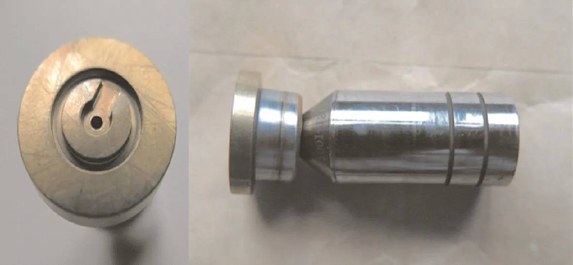
Fig.1 Piston and slipper.
Based on the Reynolds equation of lubrication,Kazama and Yamaguchi14presented a time-dependent mathematical model for slipper/swash plate under film lubrication condition.The model considered the effects of eccentric and moment loads,supply pressure and rotate speed on the friction,flow rate and power losses.Fang15introduced a method to evaluate the lubrication characteristics between the piston and cylinder in a swash plate type axial piston pump-motor under mixed lubrication conditions.
Using the Reynolds equation of lubrication,Tsuta et al.16analyzed the slipper dynamics in a piston pump,where the effects of slipper spin,tangential velocity over the pump axis,angular and radial pressure distribution were considered.In view of the complexity of the hydraulics and dynamics of a piston pump,Wieczoreck and Ivantysynova17,18developed a package called CASPAR which employed the Reynolds equation of lubrication and the energy equation in differential form.
Deeken19analyzed the factors affecting friction by simulation.Manring et al.20studied the dynamics of a slipper/swash plate.Brajdic-Mitideri et al.21focused on the low friction pad bearing in a two-dimensional Cartesian coordinate system,taking fluid compressibility into account.Houzeaux and Codina22presented a numerical strategy for the simulation of a gear pump.Because the two gears of the pump are rotating,the intersection between them changes with time.The problem caused by the changing computational domain is resolved by the ALE method.
Niels and Santos23formulated a numerical model based on Reynolds equation to minimize the friction of tilting pad and the results showed that a large amount of energy can be saved using low length to width ratio of the cavity.Analytical solution for slippers with multiple lands was outlined in Refs.24–26and more clearly defined in Ref.27.In these studies,the authors considered the flow only existing in radial direction,and the effect of tangential velocity was neglected.Bergada et al.28analyzed the pressure distribution,leakage,force,and torquebetween the cylinder andthe port plateof an axialpiston pump.Kumar et al.29described the static and dynamic characteristics of a piston pump slipper with groove.Three dimensional Navier–Stokes equations in cylindrical coordinates were applied to the grooved slipper/swash plate gap.
Due to complexities in geometry and physics,CFD pump simulation has historically been very challenging and time consuming,especially for cases with cavitation.Ding et al.30presented a novel CFD methodology and an advanced cavitation model,through which grids for the moving and stationary parts are created as separate volumes.It is an efficient,accurate and robust solution if implemented properly.
Most literatures studied the slipper performance and took the effect on the oil film thickness and friction into account in design and analysis.Even though a degree of non-flatness was essential to ensure the perfect performance of the slipper,the increment of film thickness with reduction of slipper non-flatness was very small.3,5The oil film thickness of slipper is mainly affected by the orifice size,5,9,10over-clamped ratio6,8–10,number of full lands11–13,20and running conditions.29,31,32Slippers operate perfectly with the orifice blanked and,indeed,are generally most stable in this condition.Introduction of the orifice in under-clamped slippers increases the clearance,8and slippers with no orifice have the greatest resistance to tilting couples and the minimum film thickness.10Bergada presented an analytical solution for slippers with multiple lands,and Kumar outlined it more clearly in Refs.29,31.In the conclusions of Bergada and Kumar,the oil film clearance is greater for a single-land slipper than a double-land slipper.Oil film thickness is closely related to the running conditions such as rotate speed and load pressure.
Leakage is the most important factor related with hydraulic efficiency of piston pump,and almost half of the leakage is derived from slippers.Not much leakage is necessary for good lubrication and mechanical efficiency,and a tradeoff between mechanical and volumetric efficiency must be made.Leakage is affected obviously by the oil film clearance and running conditions,11–13but not very significantly by the relative position of swash plate and slipper,1sealing land number and width.22,29,31Bergada et al.32presented an equation to evaluate leakages in all piston pump gaps.
Force and torque analyses always are the focus of researchers,24–26and slipper mechanics are decided by almost all the design factors,so it is difficult to describe their effects separately.Slipper tilt torque is closely related to its stable operation.Herein,we only reference researches on tilt torque analysis.29,31Similar with the leakage,tilt torque is affected by the relative position of slipper and swash plate,which is different when they are and are not parallel.Degree of nonflatness,7orifice size,9,10swash plate angle,eccentric or moment loads,supply pressure and speed of rotate14will change the tilt torque simultaneously.Tilting couple due to friction on the slipper running surface is much smaller than the ones of piston-cylinder pair and piston-slipper pair.7
Analytical,experimental,and numerical methods are the three normal research approaches on piston and slipper.Previous studies commonly used analytical and experimental methods.11,13The advantage of analytical approach is that explicit equations allow a direct understanding of the effect of dimension changes and operating conditions on hydraulic pump.Some studies were totally experimental,20and the results can directly express the effects of different designs on slipper performance.
With the development of computational and numerical technology,analysis-based mathematical model and numerical method are becoming the most common approaches.24–27The mathematical analysis of the slipper with groove is too complex to be solved analytically without further approximation.
Slipper performance has close relation with fluid film lubrication,and for more than one century,fluid film lubrication problems have traditionally been analyzed based on the Reynolds equation.23–28However,in recent years there has been a growing application of the full Navier–Stokes equations to solve the lubrication problems.Because in some conditions,assumptions used by Reynolds equation are invalid,for example,fluid inertia is significant,and the fluid responds viscoelastically.33In systems with complex geometry,34,35Reynolds equation is limited only to the thin film contact itself,but the Navier–Stokes equations can be applied throughout.22Furthermore,increasing availability of user-friendly commercial CFD codes(ANSYS,FLUENT and COMSOL)based on the Navier–Stokes equations has greatly reduced the effort to implement Navier–Stokes solutions.29,31
With respect to the problem of moving mesh in finite element method,Arbitrary Lagrangian–Eulerian(ALE)formulation has the advantages of both Lagrangian and Eulerian description.Recently,ALE method has been successfully applied to moving boundary problems in consideration of a rigid-body structure.35–37Special reference that needs to be pointed out is the gear pump rotate simulation conducted by Houzeaux and Codina22based on the FEM and ALE method,while no evidence shows that there is similar utilization on piston pump slipper analysis.
2.Mathematical approaches
2.1.Governing equations and boundary conditions in Eulerian formulation
Fig.2 shows a schematic drawing of the piston/slipper assembly,inner hollow piston/slipper and swash plate clearance,and the relative movements between slipper and swash plate are also outlined.The OXY is coordinate system in the slipper with the origin O.Cross section C–C illustrates the computational domain of piston and slipper.h1,h2and h3represent the thickness of film,height of groove and length of slipper orifice,respectively.d1is the diameter of the slipper orifice.l and d2refer to the length and diameter of piston orifice.r1,r2,r3and r4show the radiuses of the non-sealing land,inner sealing land,groove and sealing land,respectively.θ is the reference angle measured counterclockwise from the positive coordinate of X axis to the line.The computational domain Ω has boundary Γ ={ΓA,ΓB,Γin,Γout}where ΓA,ΓB,Γinand Γoutare slipper,swash plate,inlet,outlet boundary,respectively.
We notice that the computational domain includes the nonsymmetrical geometry of vented slot.Furthermore,tangential velocity acting on the slipper will create a flow field below the slipper which cannot be considered symmetric in radial direction.Therefore,it is necessary to consider a three dimensional computational domain.
In order to simplify computation,the following assumptions are made:(1)Flow is laminar.(2)The slipper/swash plate clearance is uniform.(3)Steady conditions are considered.(4)Tangential velocity is taken into account.(5)Swash plate tilt angle is always zero.
The continuity equation and conservative form of Navier–Stokes equations in Eulerian formulation are given as Eqs.(1)and(2).Additionally,the boundary conditions are presented as Eq.(3).

where u is the velocity of fluid,t the simulation time and T the total simulation time.

where p is fluid pressure,ν the kinematic viscosity andfthe body forces caused by rotating of the slipper,which should not be neglected because high speed rotation will affect flow and pressure distribution.And the variation of the fluid density also should be considered in high pressure environment.Here,we consider the Navier–Stokes equations in a moving domain Ω(t)X[0,T],which has boundary Γ.

Fig.2 Diagram of computational domain.

Boundary conditions are as follows:
where u(x,y,z,t)is the velocity of fluid as described in Eq.(1)with the initial velocity u0when t=0,Ω(0)the computational domain when the variable t=0,r(x,y,z,t)the position vector, w(x,y,z,t) boundary velocity, ^n normal vector,ω(x,y,z,t)angular velocity of slipper,σ(x,y,z,t)stress tensor,Pinthe inlet pressure,and Poutthe outlet pressure.
2.2.Governing equations and boundary conditions in ALE formulation
Because effects of rotate speed,body force,and viscosity of the liquid cannot be neglected,the Navier–Stokes Eqs.(1)and(2)should be solved in the moving domain.It is most convenient using the ALE method to transform the moving domain of grooved slipper/swash plate into a fixed reference domain.
For any function g(x,y,z,t)expressed by Eulerian formulation,we can transform it into gr(xr,yr,zr,t)expressed by ALE formulation.35The transformation process is defined by Eq.(4).
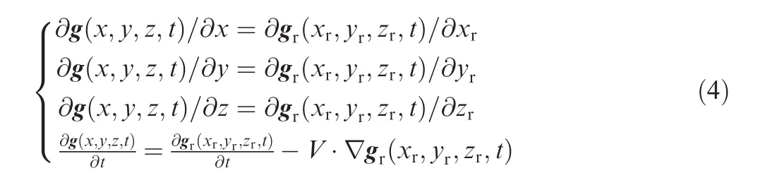
where V is the domain velocity.
According to the transformation of functions given in Eq.(4),the Navier–Stokes system can be converted from a variable domain Ω(t)X[0,T]to a fixed reference domain Ω(0)X[0,T]shown as Eq.(5),and the corresponding boundary conditions are given as Eq.(6).
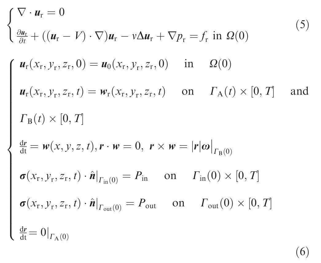
where?Ω(0)=Γ and the corresponding variables with the subscript r in Eqs.(5)and(6)cover the same interpretations as in Eq.(3),but for ALE formulation.The variable domain problem can be solved by solving a sequence of fixed reference domain problems.The modified equation is defined in a fixed domain and we can solve this problem by any of the available standard methods.
2.3.Solution technique
In order to get the discretization results of Eq.(5),we should start with considering the weak form of the problem in space–time slab Ω(t)X[tn,tn+1],which is shown as Eq.(7).
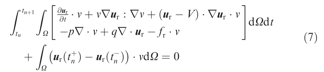
where v and q are the test functions,and[tn,tn+1]is the discretized time sliceimposes the continuity of the velocity at tn.
Eq.(5)are nonlinear convection–diffusion equations,and such equations are unstable if discretized using the Galerkin finite element method.Stabilized finite element methods are therefore necessary in order to obtain physical solutions.In this work,we select the Galerkin-least-squares(GLS)as the stabilization approach for the finite element approximation of the ALE equations,shown as Eq.(8).
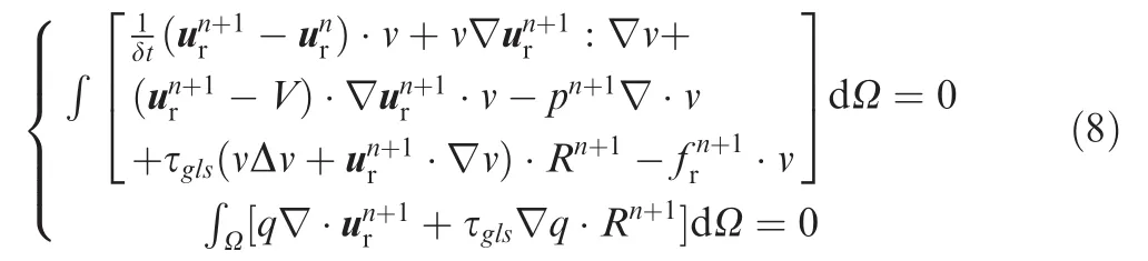
where τglsis a numerical parameter,and R the residual.Ref.38introduced the definition of these two parameters.
3.Geometry and validation of CFD model
Two approaches are utilized to validate the CFD model.One is mechanics validation,and the other is hydraulics validation.The CFD model presented in the paper is developed in COMSOL(Fig.3).In order to consider the orifice effects on leakage and pressure distribution,the model covers the orifice section of inner hollow piston,and the swash plate tilt angle is assumed always to be zero.Fig.3 shows the grid shape and density of computational domain.To save the CPU time,we created un-uniform grids within the computational domain.Grids among the oil film between slipper and swash plate are denser than the ones among the groove and orifice.
The model is discretized by a tetrahedral grid,and the grid size in radial and circumferential direction is uniform,but a very fine grid is used inside the clearance to simulate the fluid flow.
3.1.Mechanics validation
The inlet pressure is maintained at a constant value given by Pin.During the operation of the slipper,a fluid pressure profile is generated between the slipper/swash plate clearances.This pressure profile can separate the bearing from the surface to avoid metal to metal contact,and the applied load from inlet pressure Pinwill resist this separating force.

Fig.3 CFD model of slipper.
Generally,separating force and applied load must have a balance.This research compares the two forces to conduct the mechanics validation.The applied load will be constant when the Pinis constant,and the separating force is closely related with the geometry and running condition.
Accordingly,the slipper dimensions are listed as follows:non-sealing land inside radius r1=1.5 mm;non-sealing land outside radiusr2=3.4 mm;sealing land inside radius r3=4.4 mm;sealing land outside radius r4=7.7 mm;slipper orifice diameter d1=1 mm; piston orifice diameter d2=1.2 mm;height of groove h2=0.8 mm;slipper orifice length h3=0.8 mm;piston orifice length l=11 mm.
The film thickness h1has significant effect on the separating force,which is obtained through Eq.(9).Herein,the calculation of h1does not take the effect of orifice into account.

where U is the relative velocity between slipper and swash plate,and μ the dynamic viscosity of the oil fluid.Hydrodynamic parameter G is only influenced by the temperature(which effects the dynamic viscosity μ)and irrelative with rotate velocity and outlet pressure,which is consistent with Hooke's theory.10Based on the oil film thickness obtained through simulation in COMSOL,hydrodynamic parameterG can be calculated repeatedly under the different temperature(dynamic viscosity).Furthermore,the values of h1could be calculated under different running conditions,as listed in Table 1.

Table 1 Film thickness under different conditions.
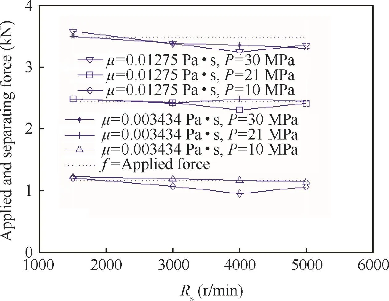
Fig.4 Separating force on slipper.
Comparing the applied load calculated by analytical method(dashed line in Fig.4)with separating force obtained from CFD simulation(solid line in Fig.4,and Rsis rotate speed)at the different dynamic viscosity μ and pressure P,

Fig.5 Leakages among slipper clearances.
we can see that the applied load and separating force are approximately equal,which is important for the balance of the slipper.
3.2.Hydraulics validation
Similar to the separating force,the volumetric flow-rate Q of fluid into the slipper clearance,which also can be described as the leakage,is affected by film thickness significantly.
Leakage can be approximated by a well-known analytical Eq.(10).
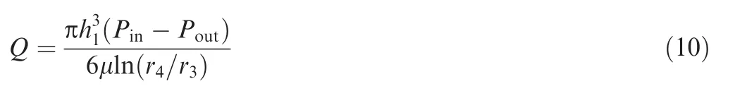
Comparing the leakage obtained from CFD simulation(Fig.5)with the one derived by analytical method(Eq.(10)),we can see there is not a very good match between the two results,while the varying tendency is consistent when considering the effects of viscosity,inlet pressure and rotate speed.Herein,it should be notified that the running conditions had been considered when we calculated the film thickness h1(Table 1)by analytical method,as mentioned above.The effects of orifice size,groove width and radiuses were neglected.It is interesting that higher pressure will not cause larger leakage,only because the oil film becomes lower with the increasing of pressure.
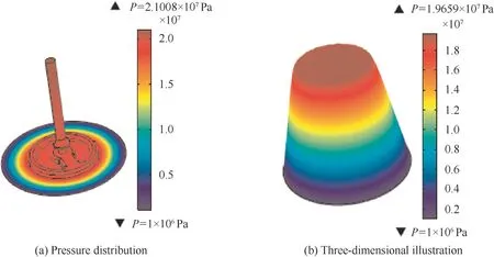
Fig.6 Simulation results of pressure distribution.
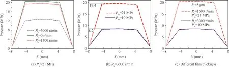
Fig.7 Effect of running condition on pressure distribution.
4.Results and discussion
All the graphs in this section are obtained indirectly via CFD(COMSOL).When simulation under specific running condition are finished,the desired data are obtained by the specific tools supplied by COMSOL.
4.1.Pressure,friction and tilt torque
4.1.1.Pressure distribution
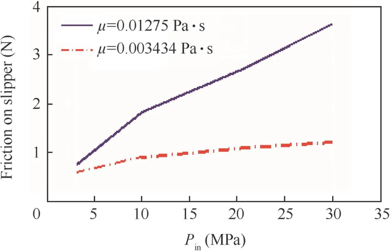
Fig.8 Friction on slipper.
When analyzing the pressure under static conditions,we realize that pressure inside the clearance is symmetric in X and Y direction.However,pressure distribution is unsymmetrical under dynamic conditions,which is caused by the body force when rotating at high speed,and the unsymmetrical structure of the slipper clearance.
Simulation results of the pressure P(Fig.6(a))below the slipper can be visualized by three-dimensional graphs(Fig.6(b)),and the two-dimensional pressure plot of cross section cut through X axis(section C–C in Fig.2)can be obtained(Fig.7).
Fig.7 represents pressure graphs under different rotate speeds,inlet pressures,and film thicknesses.It can been seen from Fig.7(a)that at higher rotate speed(Rs=3000 r/min),there exists in X direction a 0.3 MPa pressure differential approximately inside the groove.Such pressure differential is smaller in lower speed,and is zero under static condition.Obviously,body force of liquid causes the unsymmetrical pressure distribution.Fig.7(b)shows pressure under different inlet pressure,and it can be seen that lower Pinwill deliver higher pressure reduction ratio along the orifice and lower hydraulic efficiency simultaneously.When comparing Fig.7(b)and(c),we can see that pressure is not much affected by the film thickness.
4.1.2.Friction and tilt torque
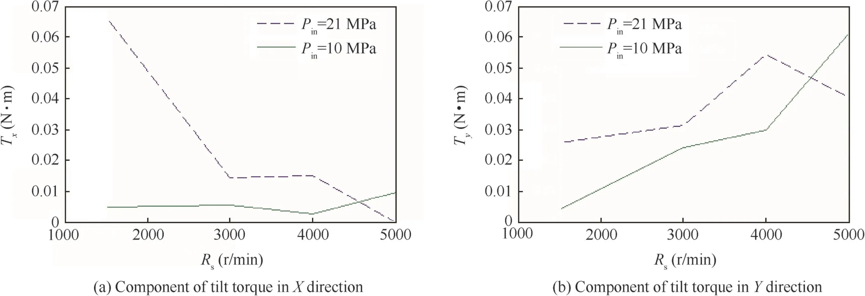
Fig.9 X and Y axis tilt torque at μ=0.01275 Pa.s.
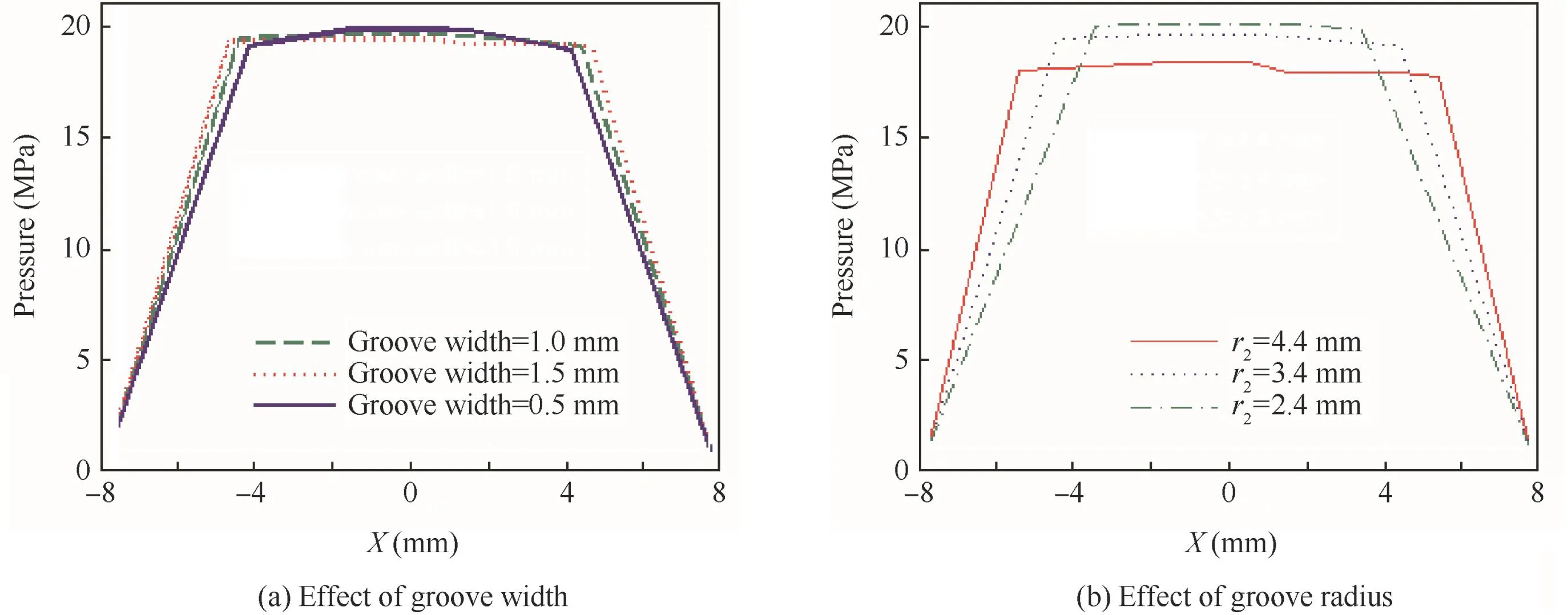
Fig.10 Pressure graphs under conditions Rs=3000 r/min and Pin=21 MPa.
Under ideal running condition without metal to metal contact,friction between the slipper and swash plate is mainly caused by the shear stresses of the fluid,which is affected by the film thickness and oil viscosity.Fig.8 presents the friction at different viscosity μ,and it can be seen that at higher viscosity,friction increases significantly with the increasing of inlet pressure,while friction is not sensitive to Pinunder lower viscosity condition.

Fig.11 Oil film thickness under different orifice diameters.

Fig.12 Effect of groove dimensions on leakage.
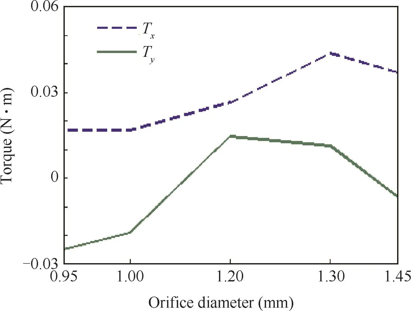
Fig.13 Effect of orifice diameter on tilt torque.
The tilt torque is mainly caused by the unsymmetrical pressure distribution in radial direction and the friction in tangential velocity direction.Similar to the friction,tilt torque is also affected by the inlet pressure,rotate speed,viscosity and film thickness.Fig.9 shows the tilt torque of X axis(Tx)and tilt torque of Y axis(Ty)at different rotate speeds and inlet pressures.It can be seen that at higher inlet pressure(Pin=21 MPa),Txdecreases when rotate speed increases,while Tyis less dependent on rotate speed,and becomes smaller when rotate speed is very high.Under lower inlet pressure,contrary conclusion can be derived based on the graphs of Fig.9.Txis mainly caused by the unsymmetrical structure,and the effect of geometry will become smaller when Pinand Rsincrease.Tyis mainly caused by the centrifugal force;therefore it is normal for Tyto become bigger with rotate speed increasing.
4.2.Effects of geometry(width,radius and orifice size)
4.2.1.On pressure distribution
Fig.10(a)presents the pressure graphs for three different groove widths,and it can be seen that there is not significant influence on the pressure.Fig.10(b)shows the comparison results of three graphs under different groove radiuses,and lower groove radius will cause higher pressure inside the groove.
4.2.2.On film thickness
Herein,the effects of groove width and radius on film thickness are neglected,and only orifice size is considered.There is no doubt that increasing orifice diameter will lift the slipper and enlarge oil film clearance.Fig.11 presents a possible approach to express the oil film and its relevant parameters quantitatively,which is important for the piston pump design.
4.2.3.On leakage
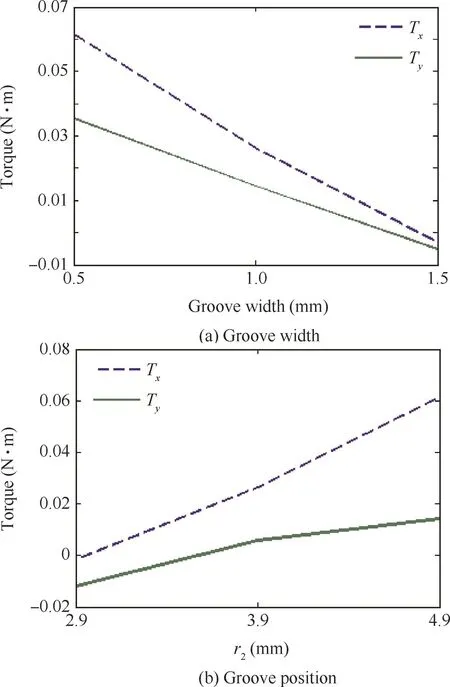
Fig.14 Effects of groove dimensions on tilt torque.
Fig.12 shows the effects of groove dimensions on leakage.From Figs.10 and 12,it can be seen that groove width has low influence on both the pressure distribution and leakage,while groove position is very significant,and increasing groove radius will deliver both more leakage and much flatter pressure distribution inside the groove.A trade off must be considered in design.
4.2.4.On tilt torque
Unlike the effect of orifice diameter on leakage(Fig.11),tilt torques of X and Y axis do not increase monotonously with the increasing of orifice size(Fig.13).We do not expect that the turning point obtained based on the simulation result is exactly similar with the real condition,but it is certain that there exists an optimal orifice size for minimum leakage and maximum dynamic stability.
Groove width and radius have contrary effect on the tilt torque(Fig.14),which means that minimum groove width and maximum radius will present good and stable performance.
5.Conclusions
(1)The higher the rotate speed of the slipper is,the more unsymmetrical the pressure distribution along the radial direction of the oil film becomes. Then the friction and tilt torque on the slipper are higher as well. When the slippers are rotating at high speed,there is a noticeable pressure differential along the slipper radial direction,and the one along the angular direction,which is mainly caused by structure asymmetry,decreases simultaneously.
(2)Higher inlet pressure may not result in more leakage.With the oil film and orifice,pressure drop rate becomes lower when running at higher inlet pressure.The pressure reductions related with oil film and orifice are both important for hydraulic efficiency.
(3)The groove width does not deliver significant influence on the pressure and leakage,while groove radius does affect pressure distribution and leakage considerably.Groove width and radius have contrary effect on the tilt torque.Given that the leakage and lubrication are not considered,maximum groove width and minimum radius present good stable performance.
(4)Leakage tends to increase continuously with the orifice diameter,while tilt torques do not have similar behavior,which means that there exists an optimal orifice size for minimum leakage and maximum dynamic stability.
Acknowledgments
The authors gratefully acknowledge the support from the National Natural Science Foundation of China (No.51205007)and the Specialized Research Fund for the Doctoral Program of Chinese Higher Education(No.20131102120019).
1.Fisher MJ.A theoretical determination of some characteristics of a tilted hydrostatic slipper bearing.British Hydromechanics Research Association;1962.Report No.:RR-728.
2.B?inghoff O.Untersuchen zum reibung sverhalten der gleitschuhe in schr?gscheiben-axialkolbenmascinen.Düsseldorf:VDI-Forschungsheft, VDI-Verlag;1977.p.1–46.
3.Hooke CJ,Kakoullis YP.The lubrication of slippers on axial piston pumps.5th international fluid power symposium;1978.p.13–26.
4.Hooke CJ,Kakoullis YP.The effects of non-flatness on the performance of slippers in axial piston pumps.J Mech Eng Sci 1988;197(4):239–47.
5.Hooke CJ,Li KY.The lubrication of over clamped slippers in axial piston pumps centrally loaded behavior.J Mech Eng Sci 1988;202(4):287–93.
6.Hooke CJ,Kakoullis YP.The effects of centrifugal load and ball friction on the lubrication of slippers in axial piston pumps.6th international fluid power symposium;1981.p.179–91.
7.Hooke CJ,Li KY.The lubrication of slippers in axial piston pumps and motors-the effect of tilting couples.J Mech Eng Sci 1989;203(53):343–50.
8.Koc E,Hooke CJ,Li KY.Slipper balance in axial piston pumps and motors.J Tribol 1992;114(4):766–72.
9.Koc E,Hooke CJ.Investigation into the effects of orifice size,offset and overclamp ratio on the lubrication of slipper bearings.Tribol Int 1996;29(4):299–305.
10.Koc E,Hooke CJ.Considerations in the design of partially hydrostatic slipper bearings.Tribol Int 1997;30(11):815–23.
11.Iboshi N,Yamaguchi A.Characteristics of a slipper bearing for swash plate type axial piston pumps and motors:1st report,theoretical analysis.Bull JSME 1982;25(210):1921–30.
12.Iboshi N,Yamaguchi A.Characteristics of a slipper bearing for swash plate type axial piston pumps and motors-2 experiment.Bull JSME 1983;26(219):1583–9.
13.Iboshi N.Characteristics of a slipper bearing for swash plate type axial piston pumps and motors–III:design method for a slipper with a minimum power loss in fluid lubrication.Bull JSME 1986;29(254):2529–38.
14.Kazama T,Yamaguchi A.Application of a mixed lubrication model for hydrostatic equipment.Tribol Trans ASME 1993;115(4):686–91.
15.Fang Y.Mixed lubrication characteristics between the piston and cylinder in hydraulic piston pump-motor.J Tribol 1995;117(1):80–5.
16.Tsuta T,Iwamoto T,Umeda T.Combined dynamic response analysis of a piston-slipper system and lubricants in hydraulic piston pump.Emerg Technol Fluids Struct Fluid/Struct Interact ASME 1999;396(1):87–94.
17.Wieczoreck U,Ivantysynova M.CASPAR–a computer aided design tool for axial piston machines.Proceedings of the power transmission motion and control international workshop;2000.p.113–26.
18.Wieczoreck U,Ivantysynova M.Computer aided optimization of bearing and sealing gaps in hydrostatic machines the simulation tool CASPAR.Int J Fluid Power 2002;1(3):7–20.
19.Deeken M.Simulation of the tribological contacts in an axial piston machine.?lhydraulik und Pneumatik 2003;47(5):11–2.
20.Manring ND,Wray CL,Dong Z.Experimental studies on the performance of slipper bearings within axial-piston pumps.J Tribol 2004;126(3):511–8.
21.Brajdic-Mitideri P,Gosman AD,Loannides E,Spikes HA.CFD analysis of a low friction pocketed pad bearing.J Tribol 2005;127(4):803–12.
22.Houzeaux G,Codina R.A finite element method for the solution of rotary pumps.Comput Fluids 2007;36(4):667–79.
23.Niels H,Santos F.Reducing friction in tilting pad bearing by the use of enclosed recesses.J Tribol 2008;130(1):125–8.
24.Bergada JM,Watton J.A direct leakage flow rate calculation method for axial pump grooved pistons and slippers,and its evaluation for a 5/95 fluid application.5th JFPS international symposium on fluid power;2002.p.259–64.
25.Bergada JM,Watton J.Axial piston pump slipper balance with multiple lands.ASME international mechanical engineering congress and exposition;2002 Nov 17–22;New Orleans,(Louisiana);2002.p.69–73.
26.Park T.Lubrication analysis between piston and cylinder in high pressure piston pump considering circumferential grooves and viscosity with pressure.ASME 2008 9th biennial conference on engineering systems design and analysis;2008,July 7–9;Haifa,Israel.2008.p.435–42.
27.Bergada JM,Haynes JM,Watton J.Leakage and groove pressure of an axial piston pump slipper with multiple lands.Tribol Trans 2008;5(4):469–82.
28.Bergada JM,Watton J,Kumar S.Pressure,flow,force,and torque between the barrel and port plate in an axial piston pump.J Dyn Syst Meas Control 2008;130(1):141–8.
29.Kumar S,Bergada JM,Watton J.Axial piston pump grooved slipper analysis by CFD simulation of three-dimensional NVS equation in cylindrical coordinates.Comput Fluids2009;38(3):648–63.
30.Ding H,Visser FC,Jiang Y,Furmanczyk M.Demonstration and validation of a 3D CFD simulation tool predicting pump performance and cavitation for industrial applications.J Fluids Eng 2011;133(1):277–93.
31.Kumar S.CFD analysis of an axial piston pump fluid mechanics[dissertation].Catalunya:Department Universidad Politecnica de Catalunya;2010.
32.Bergada JM,Kumar S,Ll D.A complete analysis of axial piston pump leakage and output flow ripples.Appl Math Model 2012;36(4):1731–51.
33.Almqvist T,Larsson R.A comparison between computational fluid dynamic and Reynolds approaches for simulating transient EHL line contact.Tribol Int 2004;37(1):61–9.
34.Guo ZL,Hirano T,Gordon KR.Application of CFD analysis for rotating machinery,Part 1:hydrodynamic,hydrostatic bearings and squeeze film damper.J Eng Gas Turbines Power 2005;127(2):445–51.
35.Hirt CW,Amsden A,Cook JL.An arbitrary Lagrangian–Eulerian computing method for all flow speeds.J Comput Phys 1997;135(2):203–16.
36.Soulaimani A,Saadb Y.An arbitrary Lagrangian–Eulerian finite element method for solving three-dimensional free surface flows.Comput Methods Appl Mech Eng 1998;162(1–4):79–106.
37.Duarte F,Gormaz R,Natesan S.Arbitrary Lagrangian–Eulerian method for Navier–Stokes equations with moving boundaries.Comput Methods ApplMech Eng 2004;193(45):4819–36.
38.Codina R,Zienkiewicz OC.CBS versus GLS stabilization of the incompressible Navier-Stokes equations and the role of the time step as stabilization parameter.Commun Numer Methods Eng 2001;18(2):99–112.
Chen Juanis a lecturer at School of Mechanical Engineering and Automation,Beihang University,Beijing,China.She received the Ph.D.degree at School of Automation Science and Electrical Engineering,Beihang University in 2003.Her research interests focus on reliability of electro-mechanical products and integrated management of mechatronical systems.
Ma Jimingreceived the Ph.D.degree at School of Automation Science and Electrical Engineering,Beihang University in 2006.His main research interests are CFD simulation and accelerating life testing of hydraulic components.
Li Jiareceived the M.S.degree at School of Mechanical Engineering and Automation,Beihang University in 2014.Now he is working in AVIC Xi'an Flight Automatic Control Research Institute.His research interests include reliability of hydraulic pump and design of hydraulic pump.
Fu Yonglingis a professor and Ph.D.supervisor at School of Mechanical Engineering and Automation,Beihang University,Beijing,China.He received the Ph.D.degree from Harbin Institute of Technology in 1993.His current research interests are the construction of hydraulic testing rig and design of hydraulic parts.
31 May 2015;revised 21 August 2015;accepted 12 October 2015
Available online 23 December 2015
Arbitrary Lagrangian–
Eulerian(ALE);
Computational fluid dynamics(CFD);
Grooved slipper;
Hydraulic pump;
Navier–Stokes equation;
Performance analysis
?2015 The Authors.Production and hosting by Elsevier Ltd.on behalf of Chinese Society of Aeronautics and Astronautics.This is an open access article under the CC BY-NC-ND license(http://creativecommons.org/licenses/by-nc-nd/4.0/).
*Corresponding author.Tel.:+86 10 82339159.
E-mail address:jiming.ma@buaa.edu.cn(J.Ma).
Peer review under responsibility of Editorial Committee of CJA.
 CHINESE JOURNAL OF AERONAUTICS2016年3期
- CHINESE JOURNAL OF AERONAUTICS的其它文章
- Optimization on cooperative feed strategy for radial–axial ring rolling process of Inco718 alloy by RSM and FEM
- Measuring reliability under epistemic uncertainty:Review on non-probabilistic reliability metrics
- Optimum blade loading for a powered rotor in descent
- Experimental study of ice accretion effects on aerodynamic performance of an NACA 23012 airfoil
- Parachute dynamics and perturbation analysis of precision airdrop system
- Simulative technology for auxiliary fuel tank separation in a wind tunnel