
Prediction of cutting forces in ball-end milling of 2.5D C/C composites
2016-11-23 06:13ShanChenweiWangXiaoYangXuanxuanLyuXiaobo
CHINESE JOURNAL OF AERONAUTICS 2016年3期
Shan Chenwei,Wang Xiao,Yang Xuanxuan,Lyu Xiaobo
Key Laboratory of Contemporary Design and Integrated Manufacturing Technology,Ministry of Education,Northwestern Polytechnical University,Xi'an 710072,China
Prediction of cutting forces in ball-end milling of 2.5D C/C composites
Shan Chenwei*,Wang Xiao,Yang Xuanxuan,Lyu Xiaobo
Key Laboratory of Contemporary Design and Integrated Manufacturing Technology,Ministry of Education,Northwestern Polytechnical University,Xi'an 710072,China
Machining of carbon/carbon(C/C)composite materials is difficult to carry out due to its high specific stiffness,brittleness,anisotropic,non-homogeneous and low thermal conductivity,which can result in tear,burr,poor surface quality and rapid wear of cutters.Accurate and fast prediction of cutting forces is important for milling C/C composite materials with high quality.This paper presents an alternative cutting force model involving the influences of the directions of fiber.Based on the calculated and experimental results,the cutting forces' coefficients of 2.5D C/C composites are evaluated using multiple linear regression method.Verification experiment has been carried out through a group of orthogonal tests.Results indicate that the proposed model is reliable and can be used to predict the cutting forces in ball-end milling of 2.5D C/C composites.
1.Introduction
C/C composites are carbon-fiber-reinforced carbon composites.They offers some superior properties,such as low weight,low thermal expansion coefficient,withstanding high temperatures and high resistance to corrosion.1,2C/C composites retain room temperature properties to be more than 3000°C in the inert atmosphere,and this is the main trend of the development of high-temperature structural materials in the future.3In addition,C/C composites are capable of replacing heart valves and hip due to its excellent biological compatibility.4
There are several kinds of C/C composites according to their braided structures.One is called 2.5-dimensional(2.5D)C/C composite.The material is obtained by laminating nonwoven fabric layers and chopped carbon fiber felts one over another.A needling process transfers some fibers along the third direction,perpendicular to the layer,to prevent delamination propagation.The chemical vapor infiltration technique is used to synthesize the matrix in the preform,made of discontinuous fibers.5,6The microstructure of the 2.5D C/C composite with needle-punched felt is shown in Fig.1.Although this material is reinforced by needle punched felt,this material is strong in the fiber direction,but quite weak in the needle punched direction.This makes it easily crush.
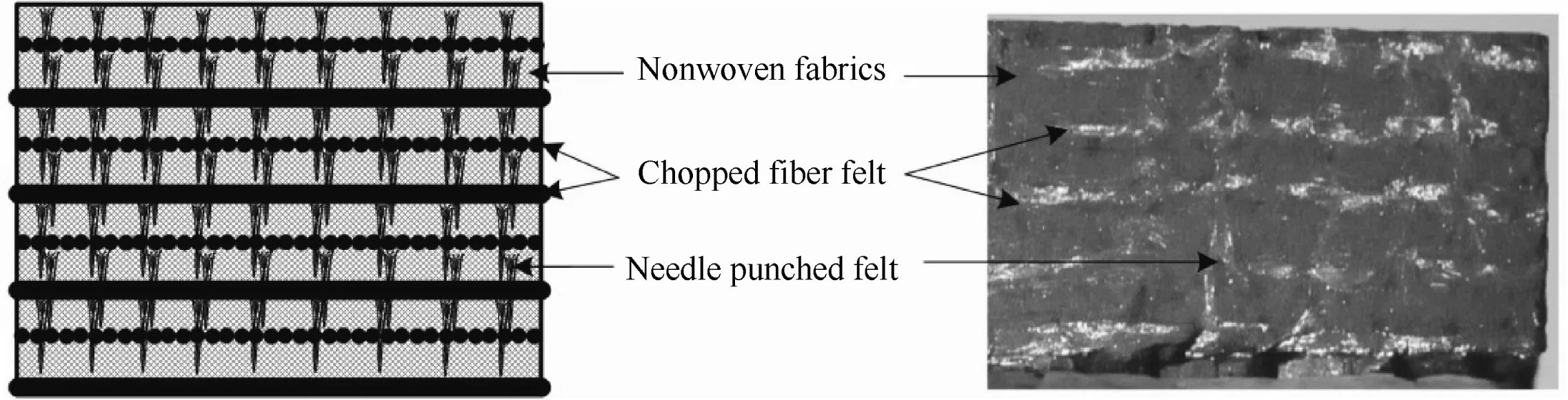
Fig.1 Illustration of 2.5D C/C composite structure.
Machining of C/C composites is a complex area.Conventional machining practices,such as turning,drilling and milling,which are a problem as the fibers and fiber direction result in an uneven cutting force and high tool wear,can still be applied to the machining of C/C composites.Although decades have passed since C/C composites appeared for the first time,there is little open literature about milling technology of C/C composites.Ferreira et al.7used ceramics,cemented carbide,cubic boron nitride,and polycrystalline diamond(PCD)to research the turning process of C/C composites.The experimental results showed that PCD was the optimal tool in finish turning,and cemented carbide tools could be used in rough turning with appropriate cutting parameters.Li et al.8proposed that the ultrasound-assisted milling relative to the normal milling could improve the surface quality of C/C composites with lower cutting temperature,cutting force and tool wear.It is helpful to process composites with high precision,high efficiency and low cost.
In milling of composites,most researches focus on carbon fibers-reinforced plastic(CFRP)composites.Hanasaki et al.9,10studied the tool wear mechanism in machining of CFRP and concluded that the fracture of carbon fiber was caused as a result of the shear stress perpendicular to the fiber direction exceeding the shear strength of fiber.Based on fiber and matrix mechanical properties,Hintze et al.11investigated machining CFRP during slot milling experiments and found that occurrence of delamination is closely related to tool wear and top layer fiber cutting angle.Turki et al.12conducted a cutting experiment to study unidirectional carbon/epoxy composites.They reached the conclusion that cutting forces increase with the increase of feed rate and cutting depth,and the forces are influenced by the fiber orientation.Krishnaraj et al.13determined the optimal cutting conditions of CFRP laminates at high speed drilling using K20 carbide drill.Chatelain and Zaghbani14studied the effect of tool geometry special features on cutting forces of multilayered CFRP laminates.They found that the special grooves reduce the axial force to approximately a null value.Hosokawa et al.15studied side milling tests of CFRP plate with two types of diamond-like carbon-coated carbide end mills with different helix angles.They found that the inclination milling with high helix angle end mill,in which the resultant cutting force acts parallel to the work surface,enables to reduce tool wear and to improve surface integrity with less delamination and fluffing.
Mahdi and Zhang16established a finite element method to predict the cutting force for the orthogonal cutting of CFRP.Zhang17presented a theoretical cutting force calculation method with fiber orientation varying from 0°to 90°for the orthogonal cutting of CFRP.Kalla et al.18simulated the cutting of CFRP with helical end mill by mechanistic modeling techniques,which can predict the cutting forces of unidirectional and multidirectional composites.Sahraie and Bahr19proposed a theoretical model based on material mechanical properties of the FRPs.Many factors are shown to affect the mechanical properties of the FRPs,including carbon fiber diameter,volumetric ratio of carbon fibers,curing conditions and so on.They concluded that their model works well when fracture plane angle is between 90°and 180°.Karpat et al.20proposed a mechanistic cutting force model for diamond cutter milling CFRP.And the cutting force coefficients in radial and tangential directions were evaluated by the sine function of fiber cutting angle.Karpat and Polat21designed a double helix end mill to eliminate the delamination of CFRP and built a mechanistic force model.By analyzing the instantaneous cutting force,Zaghbani et al.22considered that the main cause of the nonlinear change of average cutting force is the anisotropy of the material.They established a prediction model of cutting force of CFRP.Experiments showed that the measurement data and the theoretical data are in good agreement and the estimation error is approximately±12.5%.Davim and Reis23established a cutting force model using multiple regression analysis between cutting velocity and feed rate with the surface roughness and damage in a CFRP composite material.
Literature review shows that for cutting mechanism,most previous researches have been concerned with metal materials and CFRP,only a few researches have been conducted on C/C composites.Mechanistic models of machining processes are aimed at the accurate prediction of dynamic cutting forces which can estimate other quantities of the cutting process including tool life,cutter and part deflection,NC code,surface quality and process stability.Because the ball-end milling process is suitable for machining freeform surfaces and can be used in finish milling of C/C composites,it is necessary to establish a ball-end milling force model and predict the cutting force of C/C composites to improve the machining quality and efficiency.
In summary,the existing cutting force models have focused on either metal materials or CFRP.This paper presents an alternative cutting force model dedicated for ball-end milling of C/C composite materials.Influences of fiber directions on cutting forces are considered in detail.The proposed method is experimentally proven through a group of orthogonal tests.
2.Cutting force model
2.1.Deformation zones in machining of composite material
In cutting of CFRP,a chip formation area consisting of three deformation zones17is shown in Fig.2.θ is the fiber orientation angle between carbon fiber orientation and tool motion direction,acthe actual cutting thickness.aclthe nominal cutting thickness,and γethe cutting tool edge radius.The height of uncut material compressed by the tool can be treated the same as the cutting tool edge radius.Hence,the actual cutting thickness can be calculated by Eq.(1).
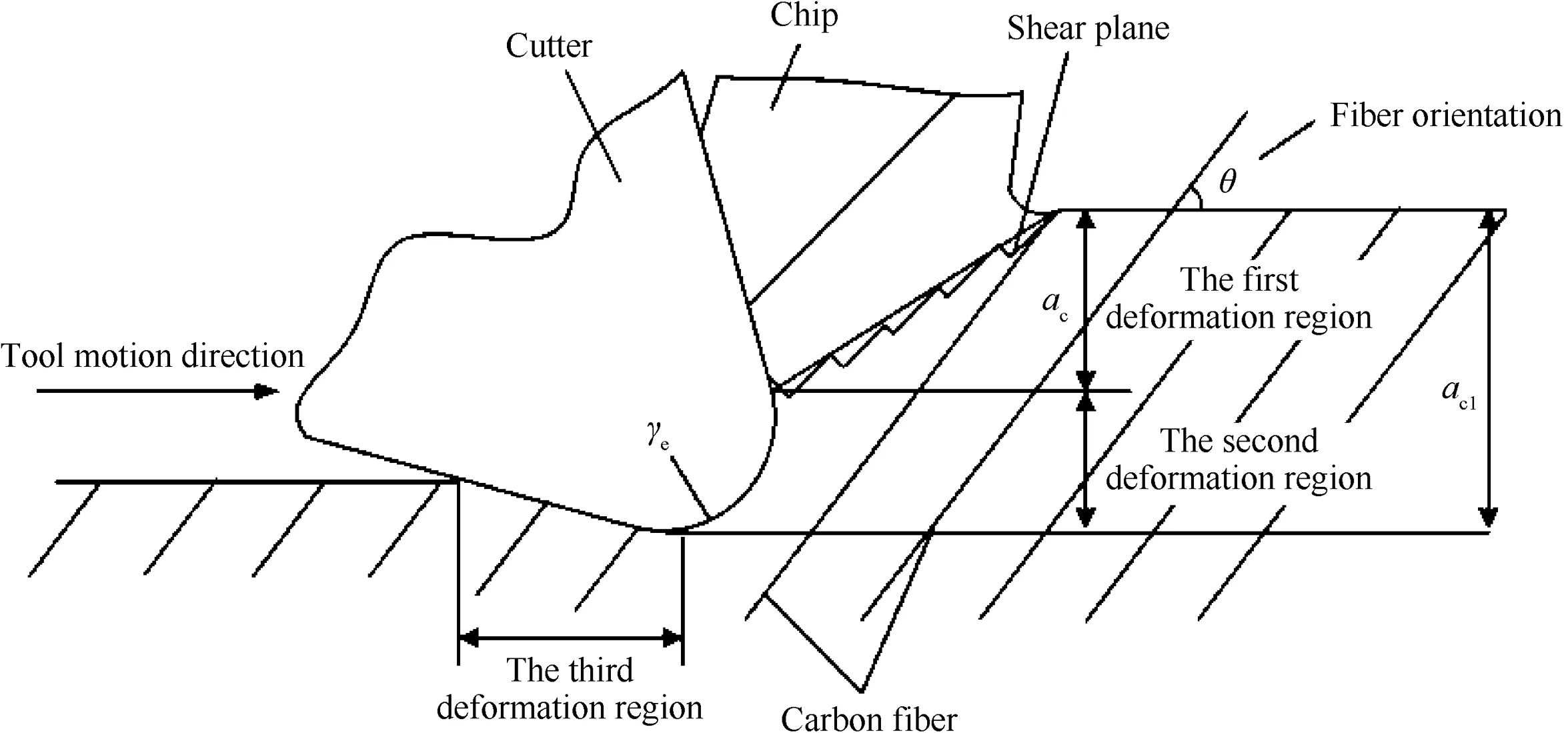
Fig.2 Three deformation regions in cutting zone of carbon fiber composite.

The first deformation region in composite cutting locates in the front of the rake face,which is the region of chip formation.Because the surface of carbon fiber is smooth,the reinforced carbon fiber of C/C composites has poor compatibility and poor bonding performance with matrix.There are many defects existing in the interfaces.As a result,the interlaminar shear strength is poor,which may lead to the fracture damage taking place on the cross sections and interlaminar interface of carbon fibers.Then it may form an approximate step-like shear plane.This cutting deformation region corresponds to the first and second deformation regions in metal cutting.The second deformation region in composite cutting locates in the front of the tool edge.A portion of material is overwhelmed at the front-end of the cutting edge when the main cutting edge passes the cutting surface.Then it will generate mixed deformations,including elastic and plastic deformation.Hence,this region is also called an extruded region.The third deformation happens between tool flank face and the machined surface.This phenomenon is caused by the elastic rebound of the pressed part in the second region.In brief,it is also called a rebound region.17
2.2.Cutting force model of 2.5D C/C composites
Many researchers employed the cutting force prediction model of unidirectional carbon fibers-reinforced plastic(UCFRP)composites to study the mechanical model of all composite materials.When the cutting directions are along the 0°and 90°fiber orientation,the cutting forces are evaluated individually for UCFRP.Besides,the resultant cutting force is evaluated based on them.According to the material structure,the cutting force of 2.5D C/C composite can also be calculated by considering the effect of the fiber direction as UCFRP.
2.2.1.Cutting force model in the first deformation region
As shown in Fig.3,the shear slip deformation process along plane AB in C/C composite cutting can be decomposed into two components.One is along plane AC perpendicular to the fiber direction.The other is along plane BC parallel to the fiber direction.During cutting process,fibers are cut off along the plane AC,and then fibers and matrix materials slide out along the plane BC and become chips.
Shear force FScan be resolved into FS1and FS2components.FS1is the cutting force vertical to the fiber direction and FS2the cutting force parallel to the fiber direction.They can be expressed by Eq.(2)when the cutting direction is along the 0°fiber direction.
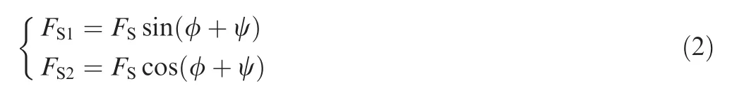
where φ is the shear angle,and ψ is the angle between the machining surface of workpiece and the working table.
According to the definition of shear force,FS1and FS2can also be expressed as
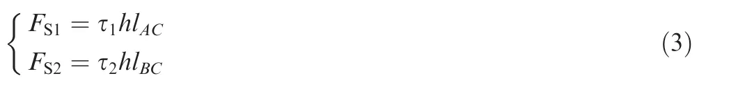
where τ1and τ2are the transverse shear strengths of carbon fiber and matrix,respectively.h is the side step.lACand lBCare the lengths of shear plane of AC and BC.
As shown in Fig.3(c),the actual cutting thickness can be given by Eq.(4).

From Eq.(4),the following expressions can be easily obtained.

Finally,one can obtain the following equation.
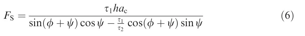
Normal force on the shear plane can be calculated by Eq.(7)according to Fig.3.

where Fy1and Fz1are the horizontal and vertical cutting force in the first deformation zone,respectively.γ0is the tool rake angle,and β the friction angle.R is the resultant cutting force,and R'its reaction force in Fig.3.
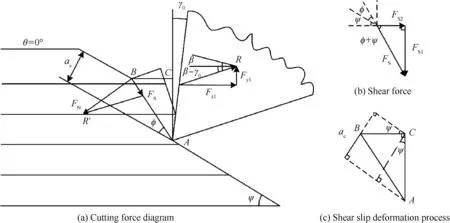
Fig.3 Illustration of the first deformation zone.
Horizontal and vertical cutting forces in the first deformation zone can be evaluated by Eq.(9)when the cutting direction is along 0°fiber orientation,
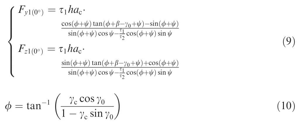
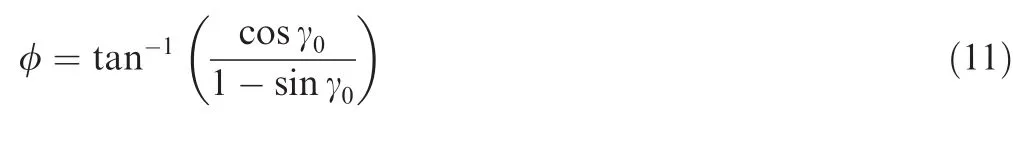
where γcis the coefficient of chip deformation.Because C/C composite is a kind of brittle material,γccan be set to be 1.
Shear angle can be evaluated by Eq.(11).
2.2.2.Cutting force model in the second deformation zone
As shown in Fig.4,the second deformation zone can be seen as a 1/4 arc of a moving cylinder rolling the machined surface.The point O is the center of the arc.
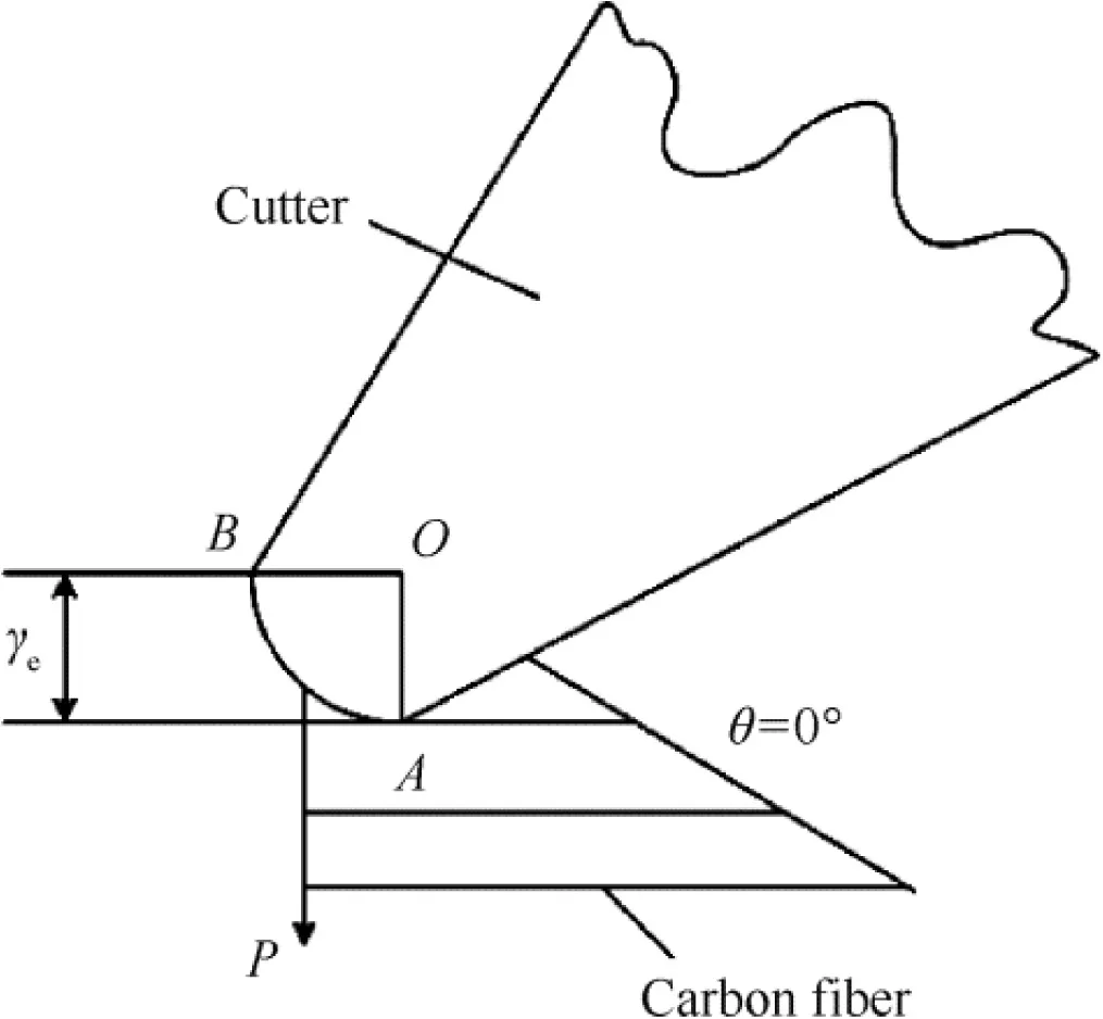
Fig.4 Cutting force in the second deformation region.
The pressure perpendicular to the fiber orientation at the arc AB is denoted as P and can be evaluated by Eq.(12)

where γeis the radius of the cutter and E*the effective elastic modulus.
The effective elastic modulus can be evaluated by Eq.(13)

where E is the elastic modulus,and μ Poisson ratio.
Because there are elastic deformations in the second deformation region,the actual pressure Prealmust be evaluated by multiplying a coefficient K with P,as shown by Eq.(14).K is a function with respect to θ.

The actual friction frealcan be evaluated by Eq.(15)

where u is friction coefficient.
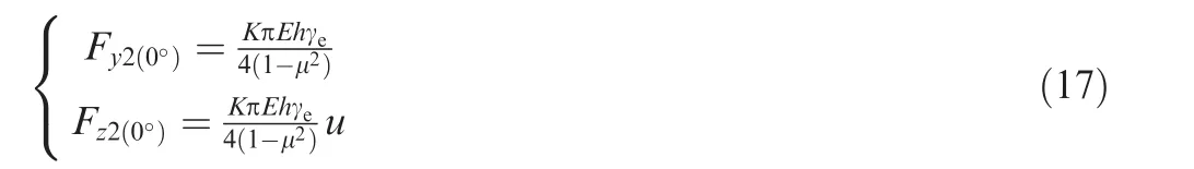
Hence,the horizontal and vertical cutting forces,Fy2and Fz2,in the second deformation zone can be given by Eq.(16)according to the actual pressure and friction,Prealand freal,and the fiber orientation angle θ.

when the angle θ is 0°,Fy2and Fz2can be evaluated by Eq.(17)
2.2.3.Cutting force model in the third deformation region
As shown in Fig.5,the third deformation zone appears under the interaction of flank face of the cutting tool and the machined surface of workpiece.The action force is caused by the elastic recovery of the workpiece materials.The pressure N acting to the workpiece material from flank face of the cutting tool is a constant for the same material.

Fig.5 Cutting force in the third deformation region.
For the convenience of calculations,it is assumed that all the materials depressed in the second deformation will rebound automatically.As shown in Fig.6,the contact length a between flank face and the workpiece can be evaluated by Eq.(18).γeis the rounded cutting edge radius,and α the tool relief angle.
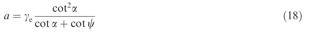
The pressure N can be evaluated by

where E3is the effective elastic modulus in the third deformation zone,and E3lt;E.
In Fig.5,f3is the friction between the tool flank face and the workpiece and it can be resolved into the horizontal force fz3and the vertical force fy3components.
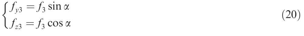
with

Based on the above equations,the following equation can be obtained.

Similarly,when the cutting direction is along the 90°fiber orientation in the three deformation regions,the cutting force can also be obtained.The cutting force for 90°fiber orientation in the first deformation zone is shown in Eq.(23).The cutting forces for 90°fiber orientation in the second and the third deformation regions equal those related to the case of 0°fiber orientation in the same deformation region.
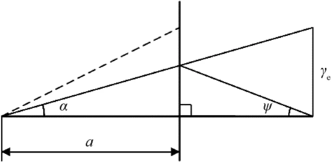
Fig.6 Contact length between flank face and workpiece.

2.2.4.Resultant cutting force model
The cutting forces of 2.5D C/C composites are associated with all the three deformation zones.Hence,it can be assumed that the resultant cutting force has a linear relationship with the cutting forces for 0°and 90°fiber orientations in three deformation regions and can be calculated by using Eq.(24).
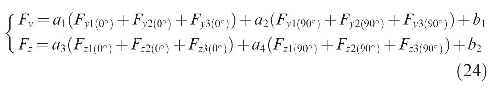
where a1,a2,a3,a4,b1and b2are the correction coefficients of linear superposition.All the correction coefficients can be evaluated by the multiple linear regression method based on the calculated and measured results.All the material parameters required in the calculation process of cutting force are obtained by mechanical tests.
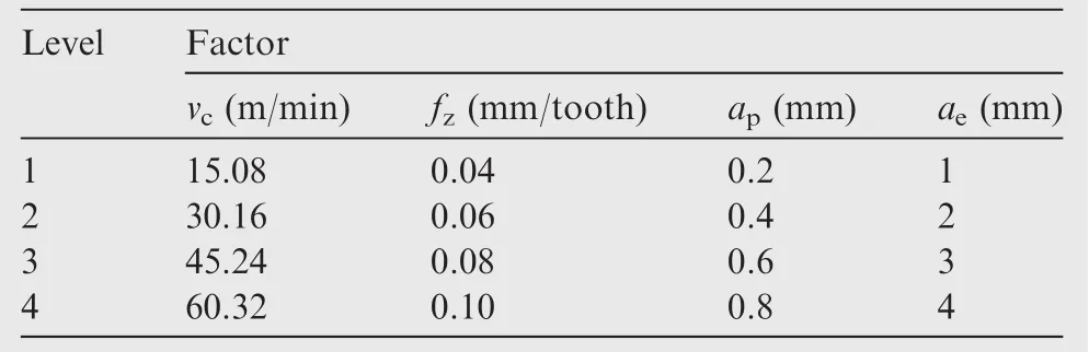
Table 1 Level table of orthogonal test.

Fig.7 Cemented carbide ball-end mill.
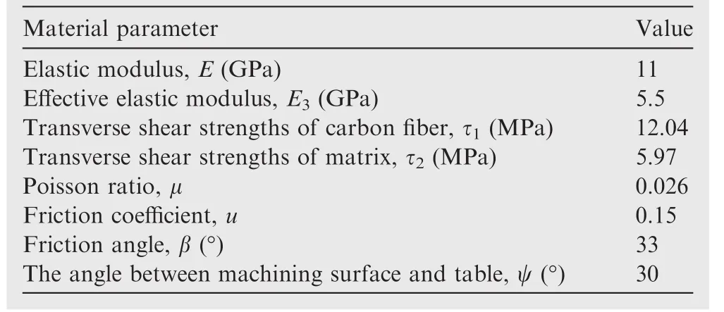
Table 2 Material parameters of 2.5D C/C composite used in test.
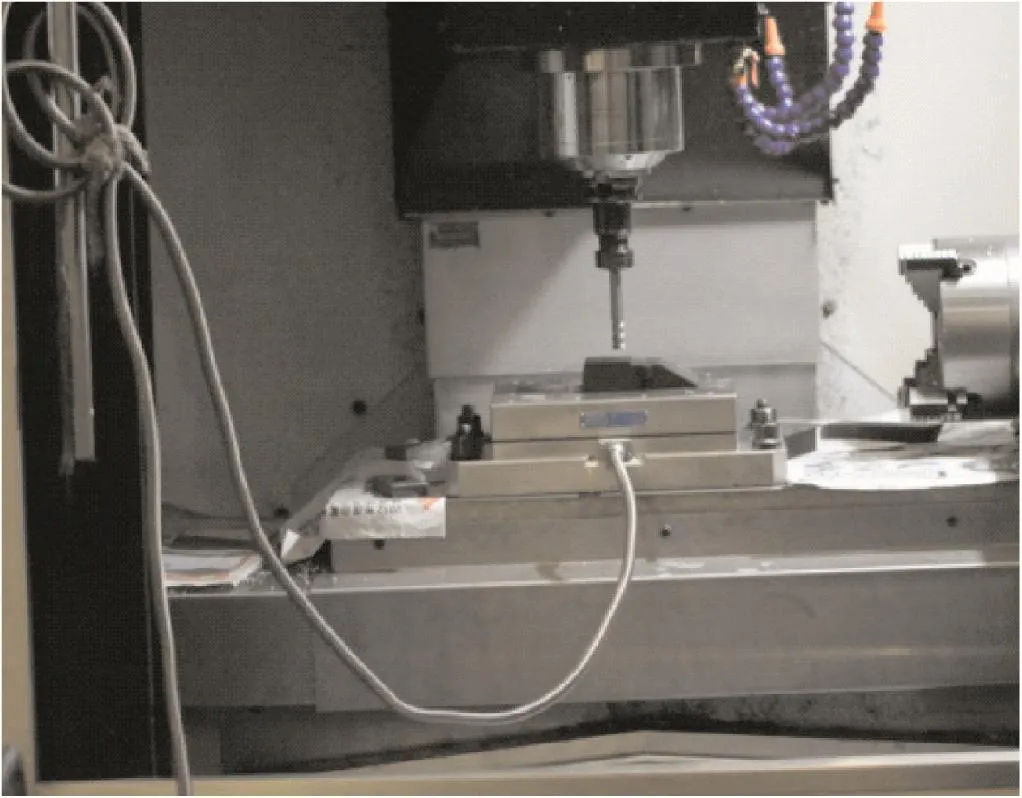
Fig.8 Experimental setup.
3.Model validation
3.1.Experimental setup
In order to validate the cutting force model,a set of tests were performed.The tests use orthogonal test design.The influencing factors are:milling speed vc,feed per tooth fz,milling depth apand cutting width ae.Each factor has four different levels.Table 1 lists each level factor of milling parameters.All the tests were conducted by using cemented carbide(K40)ballend mills with four flutes,a 40°helix angle,a 10°rake angle,a 12°relief angle and 12 mm diameter.A cemented carbide ball-end mill is schematically shown in Fig.7.
The workpiece is 2.5D C/C composite.Material parameters are shown in Table 2.A VMC850 3-axis machining center with a FANUC-OI-MB NC unit has been employed to perform milling tests(see Fig.8).Cutting force signals were measured by using a Kistler dynamometer 9255B.
3.2.Test results and analysis
The results of calculated and measured cutting forces are shown in Table 3
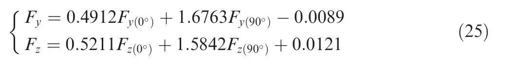
The formula of the resultant cutting force can be evaluated using Eq.(25)based on the data in Table 3.From Eq.(24)it can be seen that b1and b2in Eq.(24)can be omitted since they are very small and have no significant effect on the cutting forces.
In order to verify the accuracy of the proposed cutting force model,three verification tests were performed.Comparisons were made between the measured and calculated results,as shown in Table 4.It can be seen that the errors between the measured and calculated results are less than 10%.Hence,the proposed cutting force model is reliable and can be used to predict the cutting forces in ball-end milling of 2.5D C/C composite materials.
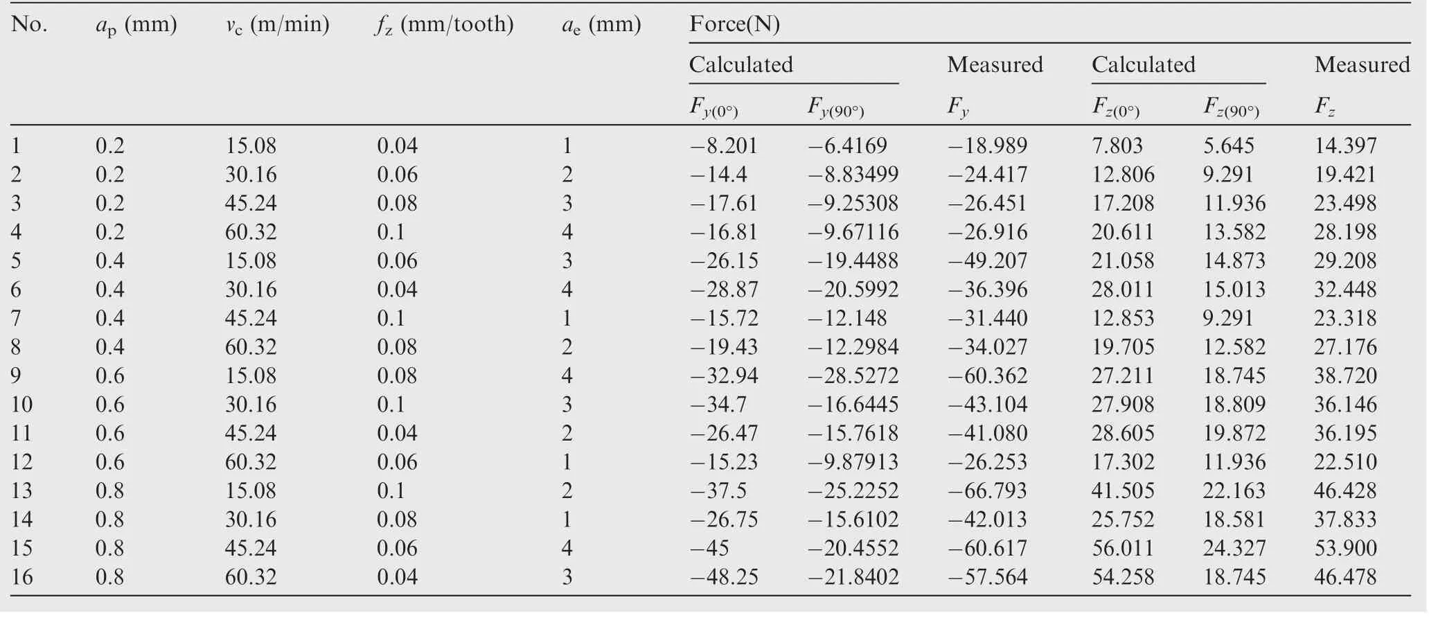
Table 3 Results of orthogonal test.
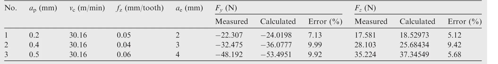
Table 4 Comparison between measured and calculated cutting forces.
4.Conclusions
An alternative cutting force model for ball-end milling of 2.5D C/C composite materials is proposed.First,the chip formation area is divided into three deformation zones.The cutting forces for 0°and 90°fiber orientations in three deformation zones are calculated individually.Then the resultant cutting force is derived using multiple linear regression method.Finally,the model is verified by a group of orthogonal tests.Results show that the maximum error is about 10%;hence,it can be reliably used to predict the cutting forces in ball-end milling of 2.5D C/C composites.
Acknowledgments
This work was supported by the National Natural Science Foundation of China(No.51105312)and the Fundamental Research Funds for the Central University of China(No.3102015JCS05005).
1.Christ K,Hüttinger K.Carbon-fiber-reinforced carbon composites fabricated with mesophase pitch.Carbon 1993;31(5):731–50.
2.Savage G.Applications of carbon–carbon composites.Carbon–carbon composites.Netherlands:Springer;1993.p.323–359.
3.Buckley JD.Carbon–carbon,an overview.Am Ceram Soc Bull 1988;67(2):364–8.
4.Windhorst T,Blount G.Carbon–carbon composites:a summary of recent developments and applications.Mater Des 1997;18(1):11–5.
5.Crouzeix L,Périé JN,Collombet F,Douchin B.An orthotropic variant of the equilibrium gap method applied to the analysis of a biaxial test on a composite material.Compos Part A 2009;40(11):1732–40.
6.Ren J,Li K,Zhang S,Yao X,Tian S.Preparation of carbon/carbon composite by pyrolysis of ethanol and methane.Mater Des 2015;65:174–8.
7.Ferreira JR,Coppini NL,Levy NF.Characteristics of carbon–carbon composite turning.J Mater Process Technol 2001;109(1–2):65–71.
8.Li ZD,Zhao B,Tong JL,Duan P.Study of carbon/carbon composite material surface morphology on ultrasonic vibration assisted milling.Key Eng Mater 2014;579–580:181–5.
9.Hanasaki S,Fujiwara J,Nomura M.Tool wear mechanism in cutting of CFRP.JSME Int J Ser C 1994;60(569):297–302.
10.Hanasaki S,Fujiwara J,Kawai T,Nomura M,Miyamoto T.Study on tool wear mechanism of CFRP cutting II.JSME Int J Ser C 2005;71(702):719–24.
11.Hintze W,Hartmann D,Schütte C.Occurrence and propagation of delamination during the machining of carbon fibre reinforced plastics(CFRPs)–an experimental study.Compos Sci Technol 2011;71(15):1719–26.
12.Turki Y,Habak M,Velasco R,Vantomme P,Khellil K.An experimental study of the routing of a unidirectional carbon/epoxy composite.AIP conference Proceedings;2011 April 27–29.Belfast,United Kingdom;2011.p.1013–8.
13.Krishnaraj V,Prabukarthi A,Ramanathan A,Elanghovan N,Senthil KM,Zitoune R,Davim J.Optimization of machining parameters at high speed drilling of carbon fiber reinforced plastic(CFRP)laminates.Compos Part B 2012;43(4):1791–9.
14.Chatelain J,Zaghbani I.Effect of tool geometry special features on cutting forces of multilayered CFRP laminates.Int J Mech 2012;6(1):52–9.
15.Hosokawa A,Hirose N,Ueda T,Furumoto T.High-quality machining of CFRP with high helix end mill.CIRP Ann Manuf Technol 2014;63(1):89–92.
16.Mahdi M,Zhang L.A finite element model for the orthogonal cutting of fiber-reinforced composite materials.J Mater Process Technol 2001;113(1):373–7.
17.Zhang HJ.Study on cutting forces of unidirectional carbon fiber reinforced plastics under orthogonal cutting.Acta Aeron et Astron Sinica 2005;26(5):604–9[Chinese].
18.Kalla D,Sheikh AJ,Twomey J.Prediction of cutting forces in helical end milling fiber reinforced polymers.Int J Mach Tools Manuf 2010;50(10):882–91.
19.Sahraie JA,Bahr B.An analytical method for predicting cutting forces in orthogonal machining of unidirectional composites.Compos Sci Technol 2010;70(16):2290–7.
20.Karpat Y,Bahtiyar O,Degěr B.Milling force modelling of multidirectional carbon fiber reinforced polymer laminates.Proc CIRP 2012;1:460–5.
21.Karpat Y,Polat N.Mechanistic force modeling for milling of carbon fiber reinforced polymers with double helix tools.CIRP Ann Manuf Technol 2013;62(1):95–8.
22.Zaghbani I,Chatelain JF,Songmene V,Berube S,Atarsia A.A comprehensive analysis of cutting forces during routing of multilayer carbon fiber-reinforced polymer laminates.J Compos Mater 2012;46(16):1955–71.
23.Davim JP,Reis P.Damage and dimensional precision on milling carbon fiber-reinforced plastics using design experiments.J Mater Process Technol 2005;160(2):160–7.
Shan Chenweiis an associate professor at School of Mechanical Engineering,Northwestern Polytechnical University,Xi'an,China.He received the Ph.D.degree from the same university in 2009.His main research interests are deformation prediction and control of thinwalled sculptured surface,CAD/CAM and C/C Composite structures'CNC machining.
Wang Xiaois an M.S.student at School of Mechanical Engineering,Northwestern Polytechnical University.His main research interest is C/C Composite structures' CNC machining.
Yang Xuanxuanis an M.S.student at School of Mechanical Engineering,Northwestern Polytechnical University.His main research interest is C/C Composite structures' CNC machining.
Lyu Xiaobois an M.S.student at School of Mechanical Engineering,Northwestern Polytechnical University.His main research interest is C/C Composite structures' CNC machining.
29 June 2015;revised 18 September 2015;accepted 16 October 2015
Available online 22 December 2015
Ball-end milling;
C/C composites;
Cutting force;
Fiber orientation;
Orthogonal test
?2015 The Authors.Production and hosting by Elsevier Ltd.on behalf of Chinese Society of Aeronautics and Astronautics.This is an open access article under the CCBY-NC-ND license(http://creativecommons.org/licenses/by-nc-nd/4.0/).
*Corresponding author.Tel.:+86 29 88492576.
E-mail address:shancw@nwpu.edu.cn(C.Shan)
Peer review under responsibility of Editorial Committee of CJA.
 CHINESE JOURNAL OF AERONAUTICS2016年3期
- CHINESE JOURNAL OF AERONAUTICS的其它文章
- Optimization on cooperative feed strategy for radial–axial ring rolling process of Inco718 alloy by RSM and FEM
- Measuring reliability under epistemic uncertainty:Review on non-probabilistic reliability metrics
- Optimum blade loading for a powered rotor in descent
- Experimental study of ice accretion effects on aerodynamic performance of an NACA 23012 airfoil
- Parachute dynamics and perturbation analysis of precision airdrop system
- Simulative technology for auxiliary fuel tank separation in a wind tunnel