
Porous Graphene-Based Electrodes for Fiber-Shaped Supercapacitors with Good Electrical Conductivity
2023-05-18 14:30XIANGRuifang向睿芳CHENXinyi陳馨逸LIUYanZHANGKunLUChunhong陸春紅
XIANG Ruifang(向睿芳), CHEN Xinyi(陳馨逸), LIU Yan(劉 巖), ZHANG Kun(張 坤), LU Chunhong(陸春紅)*
1 Shanghai Frontiers Science Center of Advanced Textiles, Donghua University, Shanghai 201620, China
2 College of Textiles, Donghua University, Shanghai 201620, China
Abstract:Graphene fibers (GFs) are ideal electrodes for fibrous supercapacitors because of their excellent mechanical and electrical properties. However, the actual specific surface area (SSA) of GFs is low due to the restacking of graphene sheets, which limits the capacitance enhancement of GFs. One of the effective ways to increase the SSA of GFs is to construct a porous fiber structure, but it disrupts the conductive pathway and adversely affects the electrochemical (EC) performance of GFs. Therefore, a wet-spun porous GF electrode coated with polypyrrole (PPy) was reported in this paper. The resulting electrode exhibits an areal specific capacitance of 31.25 mF·cm-2 and a good cycling stability with a capacitance retention rate of 95% after 5 000 charge/discharge cycles. These indicate that porous structures and PPy coating can synergistically improve the EC performance of GFs.
Key words:graphene fiber (GF); wet-spinning; polypyrrole(PPy); capacitance; supercapacitor
Introduction
In recent years, the rapid development of smart textiles has boosted an intensive investigation of flexible energy storage devices. As one of the flexible energy storage devices, fiber-shaped supercapacitors (FSSCs) have received much attention due to their high power densities, long cycle lives, fast charging/discharging rates, decent safety and reliability[1]. However, these properties of FSSCs are influenced by their electrodes, as their energy storage mechanisms including electrochemical(EC) double-layer and pseudocapacitance behaviors[2]are closely related to the materials and structures of the electrodes. In general, an ideal electrode should have a high specific surface area (SSA) and excellent electrical conductivity to achieve good EC performance for EC double-layer capacitors (EDLCs).
Graphene fibers (GFs) are the most common electrode source[3]for FSSCs based on EC double-layer behaviors. The GF is a two-dimensional carbon-based material with a hexagonal arrangement of carbon atoms through trigonal hybridization bonds. It has excellent physical properties such as a large theoretical SSA, high electron mobility and high elastic moduli[4-5]. In addition, in comparison with other electrodes (i.e., activated carbon, transitional metal oxides and conducting polymers), the exposed surface of graphene sheets tends to favor a faster ion adsorption for double-layer capacitance. In comparison with activated carbon, graphene has a higher electrical conductivity and a better crystallinity which are favorable for rapid electron transfer and EC stability[6]. However, the strong π-π interactions between graphene sheets cause the restacking of graphene sheets, thereby drastically decreasing the SSA and the electrical conductivity of graphene[7]. As a result, the actual EC performance of GFs (i.e., specific capacitances and energy densities) is not excellent enough for smart textile applications.
To enhance the specific capacitance of GF electrodes, efficient methods include increasing the SSA of the fiber and introducing pseudocapacitance. To increase the SSA, it is facile to create a large number of pores on the surface of the graphene electrode by various methods (i.e., activation[8], coating[9]and plasma etching[10]). However, porous structures tend to disrupt the conductive network of GF electrodes, which often leads to a decrease in the conductivity of the fibers and thus destroys their EC performance. To achieve a good EC performance, it is possible to simultaneously increase the SSA and the electrical conductivity of the electrode by treating porous fiber with conductive polymers (i.e., polypyrrole (PPy), polythiophene and polyaniline). In addition, the conductive polymers can also contribute partially to the capacitance by reversiblep-type orn-type doping, or de-doped redox reactions[11], and thus further increase the specific capacitance of the electrodes.
Among different conductive polymers, PPy is an environmentally friendly polymer with good electrical conductivity and stability[12]. Due to its poor solubility and dispersibility, PPy is usually synthesized by chemical oxidation of pyrrole (Py) monomers to facilitate different applications of PPy. Conductive PPy can be easily adsorbed onto the polymeric substrate as a film, which is beneficial to improving the stability of the structure. In addition, PPy can increase the capacitance of substrate electrodes by enhancing ion diffusivity and increasing the contact area of electrolytes[13-14], and provide an extra pseudocapacitance through the fast and reversible doping and de-doping redox reactions that occur during electrode reactions. Thus, PPy is a good potential conductive material to improve the EC performance of the substrate electrodes.
In this work, a porous graphene-based electrode with good electrical conductivity is prepared by activation and PPy coating. The graphene-based fiber electrodes are fabricated by scalable and cost-effective wet-spinning, followed by carbonization/activation and coating.
1 Experiments
1.1 Materials
Graphene oxide (GO) with a sheet size of about 8 μm was acquired from Hangzhou Gaoxi Technology Co., Ltd., China. Poly (vinyl alcohol) (PVA) with low viscosity, sulfuric acid (H2SO4) with a mass fraction of 98%, hydriodic acid (HI) with a mass fraction of 47%, acetic acid (CH3COOH) with a mass fraction of 99%, ferric chloride (FeCl3) and potassium hydroxide (KOH) were bought from Sinopharm Chemical Reagent Co., Ltd., China. Py with a mass fraction of 98% was purchased from Alfa Aesar (China) Chemicals Co., Ltd., China. Deionized (DI) water with resistivity of about 18.3 MΩ·cm was prepared in the laboratory with a Master-Q15 machine, China.
1.2 Preparation of GFs
GFs were prepared by a wet-spinning method. An aqueous GO solution with a mass concentration of 20 mg·mL-1was loaded into a syringe (5 mL). After defoaming, the solution was extruded by a pump into a rotating coagulation bath only containing acetic acid. Then, the obtained GO fibers (GOFs) were taken out from the coagulation bath and wound on a Teflon roller for drying at room temperature. Subsequently, the GOFs were thermally annealed at 800 ℃ for 3 h in a tube furnace to obtain pure GFs.
1.3 Preparation of porous PPy-coated activated GFs (PPy@a-GFs)
The GFs were first washed with DI water and then immersed in KOH aqueous solution (1 mol·L-1) for 12 h. Then, the fibers were dried in an oven at 60 ℃ for 30 min. Next, the fibers were thermally annealed in a tube furnace at 800 ℃ for 2 h at a heating rate of 10 ℃·min-1. After the tube furnace was cooled down to room temperature, the fibers were rinsed with DI water to remove the excessive KOH, and dried at room temperature to yield activated GFs(a-GFs). Later, a-GFs were soaked in Py solution for 20 min before the addition of FeCl3solution (0.6 mol·L-1) as an oxidation agent. The polymerization of Py occurred on the a-GF substrate. Finally, PPy@a-GFs were obtained by rinsing the fibers repeatedly with ethanol and water before being dried at room temperature.
1.4 Assembly of graphene-based FSSCs
PVA (1.00 g) and H2SO4(0.98 g) were dissolved in DI water (10 mL) to obtain PVA/H2SO4gel electrolytes. Then, two fiber electrodes made of GFs, a-GFs or PPy@a-GFs were placed parallelly to each other on a polyester substrate, respectively. The electrolytes were then dropped onto the middle section of the two aligned fiber electrodes and dried at room temperature for 12 h to yield assembled FSSCs.
1.5 Characterization
The scanning electron microscope (SEM, Hitachi SU8000, Japan) and the Fourier transform infrared spectroscope (FTIR, Nicolet NEXUS-670, USA) were used to characterize surface morphologies and functional groups within GFs, a-GFs and PPy@a-GFs, respectively. The Brunauer-Emmett-Teller (BET) technique was used to obtain SSA of graphene and activated graphene (a-G) powders based on N2adsorption/desorption isotherms, respectively. The reason for using powders instead of fibers is that the amount of fibers required for the BET test is large, and it is not possible to obtain enough fibers for the test in a short time under laboratory conditions. The ratios of micropores, mesopores and macropores were calculated asVmicro/Vtotal,Vmeso/VtotalandVmacro/Vtotal, respectively, whereVmicro,Vmeso,VmacroandVtotalare the volumes of micropores, mesopores, macropores and total pores, respectively[8].
The electrical conductivity values of all fabricated fibers were measured by a four-point method with 2400 Series Digital Source-Meter, Keithley, USA. The EC workstation (CHI660E, Chenhua Instruments, China) was used to characterize the EC performance of all fiber electrodes, including the cyclic voltammetry (CV) measurement with a scan rate ranging from 5 mV·s-1to 200 mV·s-1, the galvanostatic charge/discharge (GCD) test with an areal current density ranging from 0.1 mA·cm-2to 1.0 mA·cm-2, and the EC impedance spectroscopy (EIS) test with a frequency ranging from 0.01 kHz to 100.00 kHz. The areal specific capacitanceCA, the areal energy densityEAand the areal power densityPAof a single fiber electrode[15]were calculated according to
CA=2tI/(UA),
(1)
EA=CAU2/7 200,
(2)
PA=3 600EA/t,
(3)
wheretis the discharge time,Iis the current,Uis the potential, andAis the effective surface area of an individual fiber.
2 Results and Discussion
2.1 Structure of graphene-based fibers
As shown in Fig.1, PPy@a-GFs were prepared by a wet-spinning method for fiber formation, followed by thermal annealing for reduction. Subsequently, KOH activation was applied to yield fibers with a porous surface structure. After the activation process, the increased porosity could effectively increase the SSA of fibers to achieve a good EC performance. However, the rigid benzene ring structure of graphene nanosheets was disrupted during the activation process, which might affect the electron conduction in the graphene sheet plane. PPy coating on fiber surface was performed by polymerization of Py. With PPy coating, the long molecular chain of PPy may serve as a bridge that connects defected benzene rings to facilitate charge conduction, which contributes to the EC performance of the fiber electrode. Moreover, PPy coated on the electrode surface can improve the SSA of the fiber electrode by increasing the contact area between the fiber electrode and the electrolyte, and offer an extra pseudocapacitance through redox reactions. As a result, the capacitance of the FSSCs increases.
The SEM images of all fabricated fibers are shown in Fig.2. It can be seen that the GF has a diameter of about 40.0 μm and demonstrates irregular wrinkles on the surface shown in Fig.2(a). These surface wrinkles facilitate the formation of mesopores that contribute to the EC performance of the fiber electrode. Compared with the smooth wrinkles on the surface of the GF shown in Fig.2(b), the a-GF shows a structure with pores randomly distributed on the fiber surface shown in Figs.2(c)-2(d). These pores are beneficial to improving the fiber’s SSA. In comparison with the GF and the a-GF, the PPy@a-GF demonstrates more spherical particles on the surface shown in Figs.2(e)-2(f), strongly indicating that these particles are PPy.
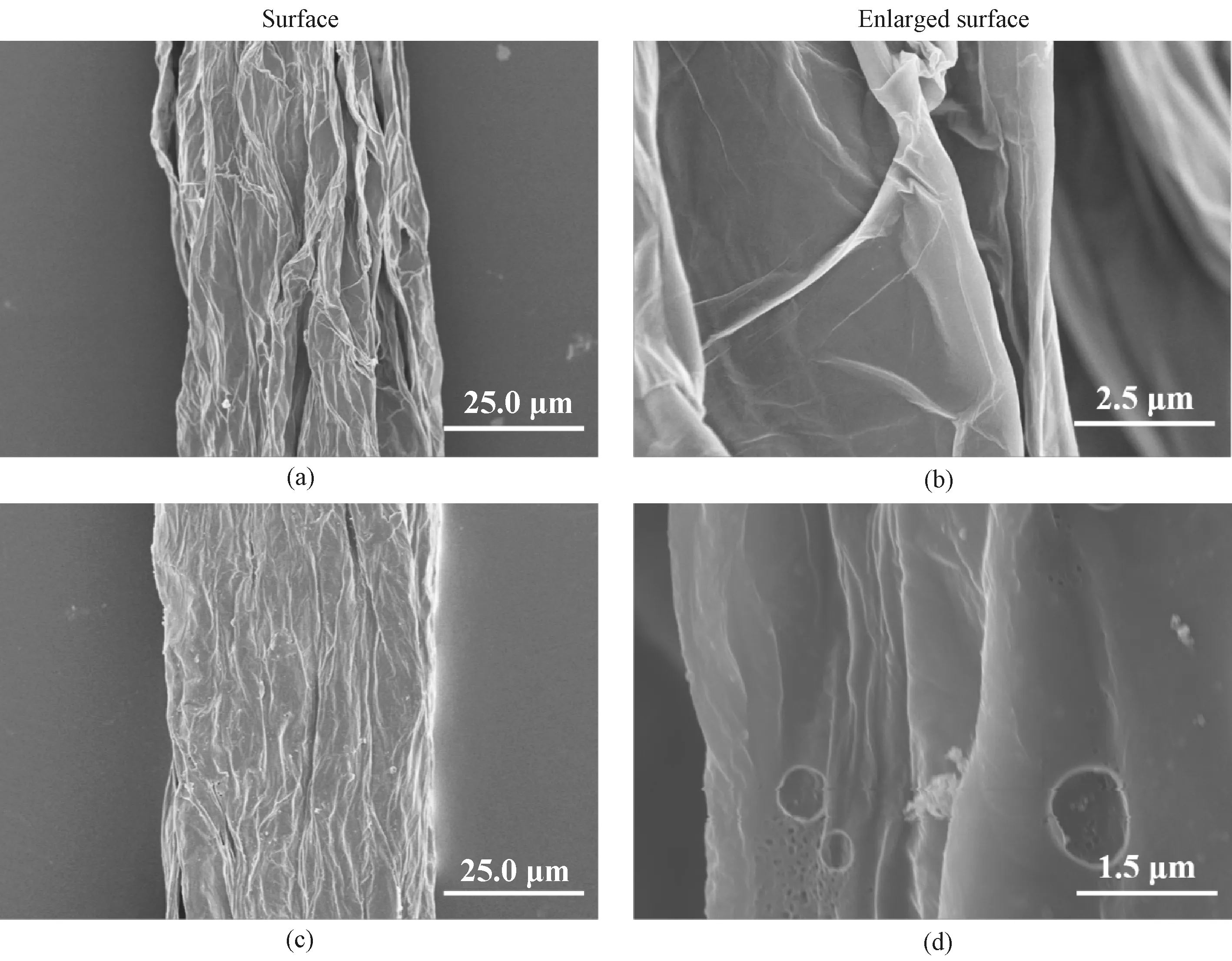
Fig.2 SEM images: (a)-(b) GF; (c)-(d) a-GF; (e)-(f) PPy@a-GF

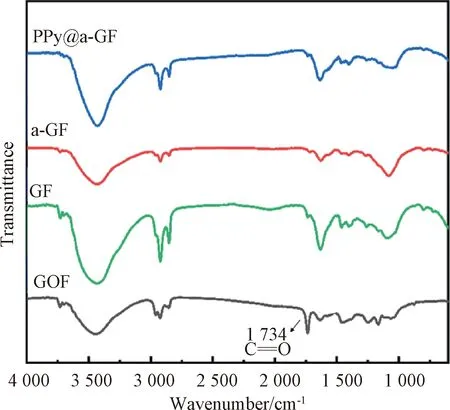
Fig.3 FTIR spectra of GOF, GF, a-GF and PPy@a-GF
2.2 Mechanisms of porous structure formation and PPy synthesis
2.2.1KOHactivationmechanismandporeanalysis
It should be noted that pores on the surface of a-GFs are formed mainly due to the reaction between KOH on the fiber surface and carbon (C) atoms of the fiber at elevated temperatures. The reaction formulas are as follows[8,15-16]:
2 C+6 KOH2 K + 2 K2CO3+3 H2,
(4)
K2CO3K2O + CO2,
(5)
K2CO3+2 C2 K+3 CO,
(6)
K2O + C2 K+CO.
(7)
When the heating temperature is below 600 ℃, the C atom of graphene reacts with KOH to form potassium carbonate (K2CO3) shown in formula (4). If the temperature is higher than 600 ℃, K2CO3decomposes to form potassium oxide (K2O) shown in formula (5). When the temperature is up to 800 ℃, K2O and the remaining K2CO3continue to react with C shown in formulas (6)-(7), eventually forming pores on the fiber surface. These pores increase the SSA of the fiber electrodes and facilitate ion diffusion and ion transfer, which enhances the EC performance of the fiber electrodes in most cases.
The BET SSA and pore size distribution (PSD) results of graphene and a-G powders were shown in Fig.4. The isotherms of both graphene (Fig.4(a)) and a-G (Fig.4(b)) powders at standard atmosphere pressure (STP) show a type IV curve and a type H2 hysteresis loop in the relative pressureP/P0range of 0.4-1.0, indicating their mesoporous structures. Graphene powders show few micropores (< 2 nm) (2.4%), and a significant amount of mesopores (2-50 nm) (51.7%) and macropores (> 50 nm) (45.9%), as shown in Fig.4(c) whose inset shows enlarged PSDs of graphene and a-G powders in the pore diameter range of 0-12 nm. After the KOH activation, a-G powders show higher volume percentages of micropores and macropores than those of graphene powders. In detail, a-G powders have 21.0% of micropores, 55.9% of mesopores, and 23.1% of macropores. Correspondingly, a-G powders have a high SSA of 87.0 m2·g-1, which is about 6.5 times as that of graphene (13.3 m2·g-1). In general, micropores in electrodes promote charge storage, mesopores facilitate charge transfer, and macropores act as ion buffer reservoirs[8]. Therefore, the hierarchical porous structure of a-GFs can effectively enhance the EC performance.
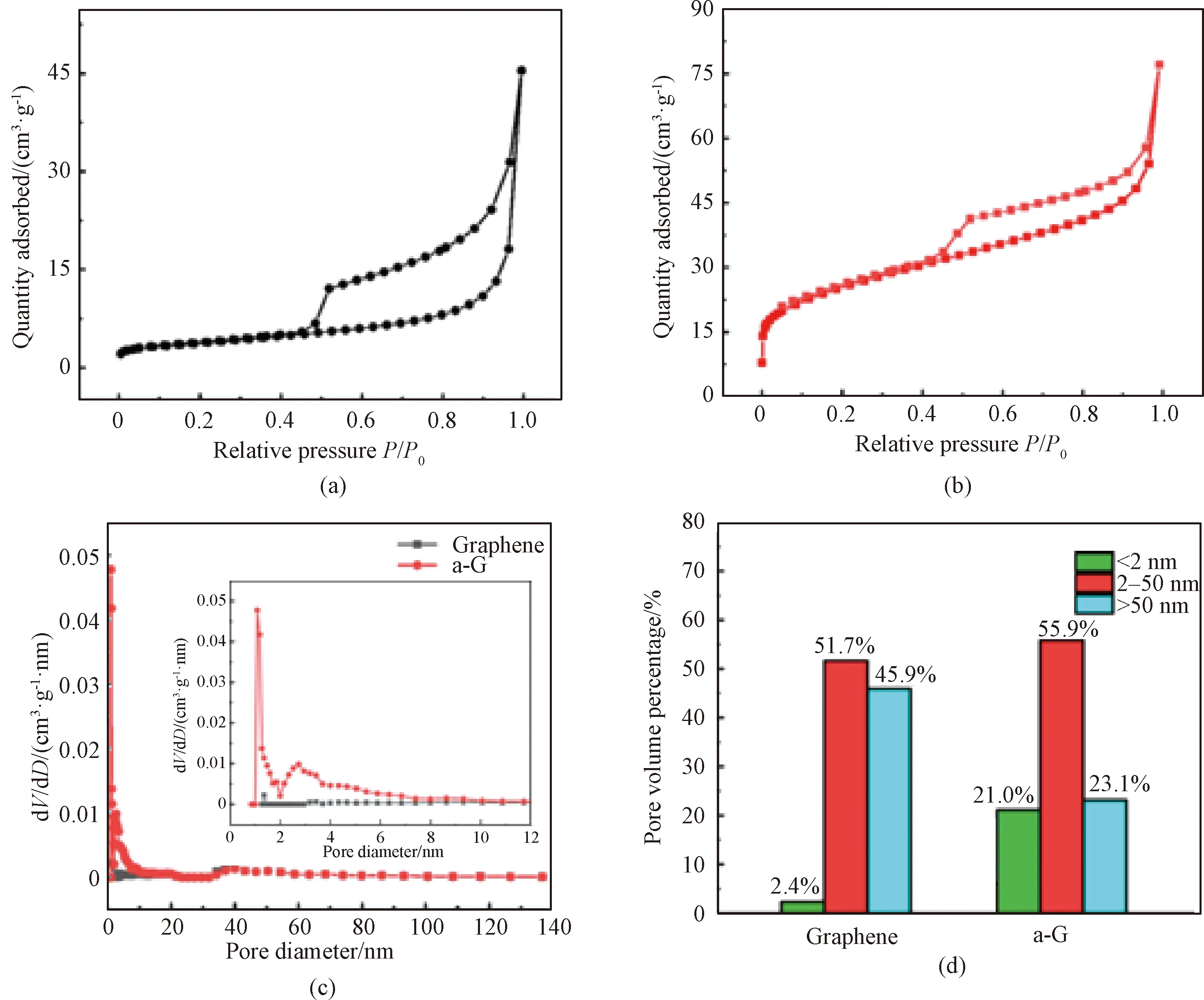
dV/dD—pore volume per unit pore size.
2.2.2PPysynthesismechanism
The synthesis of PPy is essentially sequential oxidation of Py monomer and the anion doping process. The polymerization typically consists of three stages: chain initiation, chain polymerization and chain termination. As shown in Fig.5, the Py monomer is first oxidized by the oxidation agent FeCl3, which transfers an electron into a cationic radical during chain initiation. Then, two cations combine and undergo continuous deprotonation, oxidation, coupling and deprotonation to form oligomers[17]. Finally, the chain termination determines the polymerization degree of PPy. The synthesized PPy is distributed on the fiber surface to form an effective conductive network, which contributes to the enhancement of the EC performance of the fiber electrode.
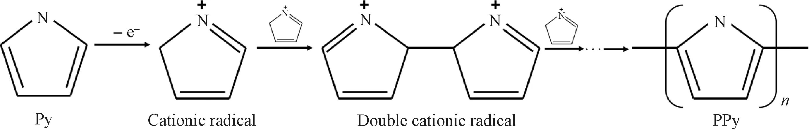
Fig.5 Polymerization mechanism of PPy
2.3 Electrical properties of graphene-based fibers
The electrical properties of all fabricated fibers are shown in Fig.6. The GFs have a good electrical conductivity of 112.70 S·cm-1mainly due to the planar hexagonal structure of graphene and the trigonal hybridization of C atoms. After the KOH activation, the electrical conductivity of a-GFs slightly decreases to 96.34 S·cm-1. This is probably attributed to the fact that the KOH etching of graphene sheets partially disrupts the continuous conductive pathway of graphene. Interestingly, the electrical conductivity of PPy@a-GFs increases to 128.25 S·cm-1after coating PPy onto a-GFs. It is referred that conductive PPy may bridge the defects caused by the KOH activation. PPy has a p-π conjugated structure with alternating single and double bonds. The electrons in delocalized π bonds can move freely along the PPy’s molecular chain, thus increasing the electrical properties of the fiber. The conductive PPy and the KOH activation contribute to the enhanced electrical conductivity and increased SSA, respectively, which are beneficial to improving the EC performance of the fiber electrodes.
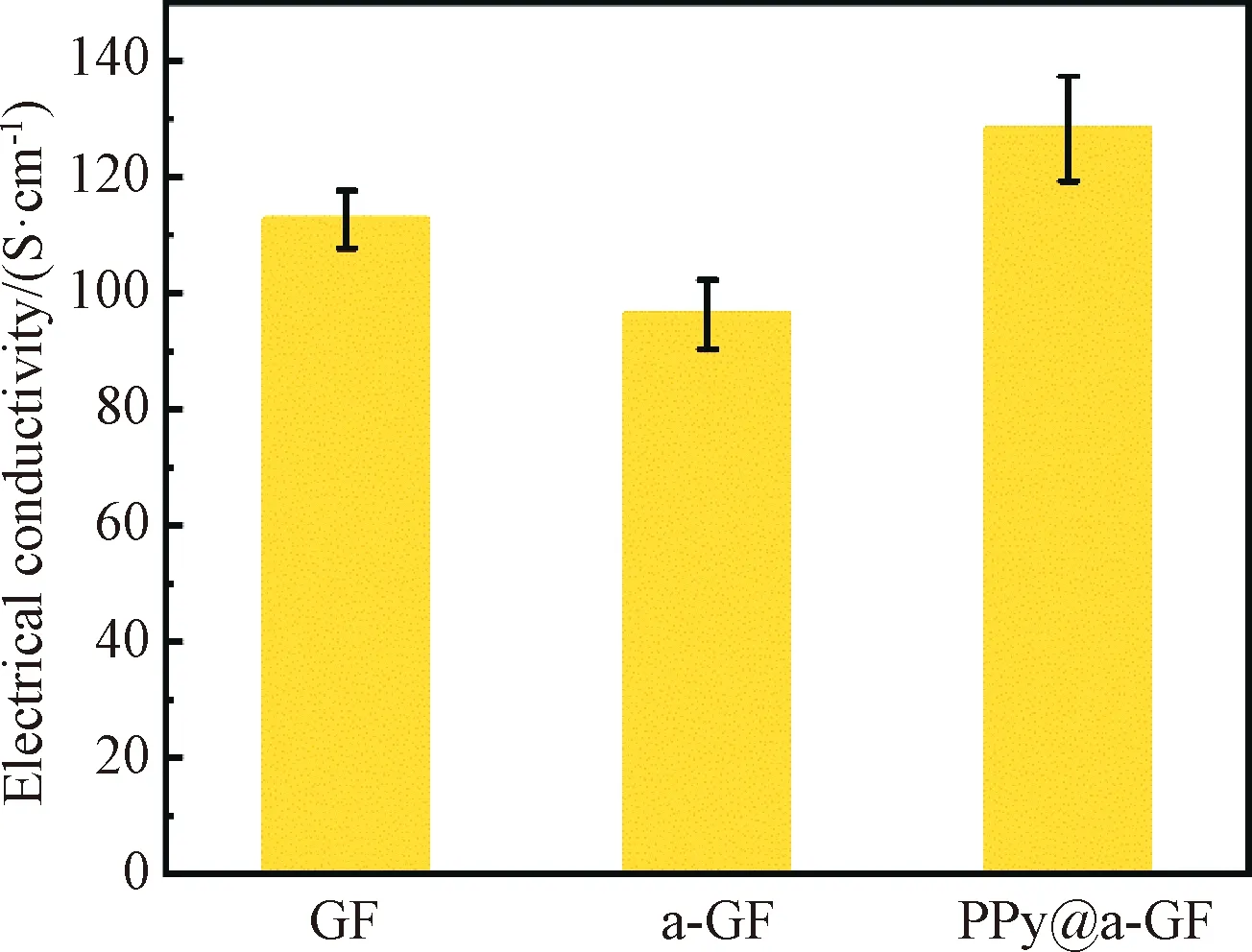
Fig.6 Electrical conductivities of GF, a-GF and PPy@a-GF
2.4 EC performance of graphene-based fiber electrodes
To better verify the synergistic effect of KOH activation and PPy coating on the enhanced EC performance of graphene-based fiber electrodes, GF, a-GF and PPy@a-GF electrodes were assembled into FSSCs. The areal specific capacitance and the areal energy density of the single fiber electrode are obtained for further analysis.
Figure 7(a) shows the CV curves of all fabricated graphene-based fiber electrodes. It is observed that the CV curve of GF electrodes is a symmetrical rectangle, indicating a typical double-layer capacitive energy storage mechanism[9]. The CV curve of a-GF electrodes is a distorted rectangle with a redox peak, which is possibly attributed to the reaction between the residual KOH molecules on the fiber surface and H2SO4in the electrolyte. The CV curve of PPy@a-GF electrodes shows two implicit symmetrical redox peaks at 0.2 V and 0.4 V, respectively. This is possibly due to the redox reaction between PPy and the acidic electrolyte. Moreover, it is obvious that the enclosed area in the CV curve of PPy@a-GF electrodes is the largest among three fiber electrodes, implying the best charge storage capacity and capacitance of PPy@a-GF electrodes.
The GCD curves of all fiber electrodes are shown in Fig.7(b). It is obvious that the GCD curves of GF electrodes show a symmetric isosceles triangle, while both GCD curves of a-GF and PPy@a-GF electrodes demonstrate obvious redox peaks. The discharge time of GF, a-GF and PPy@a-GF electrodes is 26, 47 and 125 s, respectively. PPy@a-GF electrodes possess the longest discharge time, suggesting the best EC performance. The prolonged discharge time of a-GF and PPy@a-GF electrodes correlates well with previously discussion in CV curves. In addition, the electrode voltage drops of GF, a-GF and PPy@a-GF electrodes are 20.50, 5.00 and 4.90 mV, respectively. This indicates that a-GF and PPy@a-GF electrodes have a shorter ion diffusion distance and a lower ion transport resistance than GFs.
The areal specific capacitances of all fiber electrodes are calculated based on the GCD curves and summarized in Fig.7(c). The areal specific capacitances of GF, a-GF and PPy@a-GF electrodes are 6.50, 11.75 and 31.25 mF·cm-2, respectively. It can be seen that the areal specific capacitance of GF electrodes increases after KOH activation or PPy coating, and the PPy@a-GF electrode has the largest areal specific capacitance. With the KOH activation, the porous structure of a-GFs indicates a substantially increased SSA, which corresponds to a higher areal specific capacitance than that of GFs. After coating PPy onto a-GFs, the electrical conductivity and the SSA of PPy@a-GF electrodes are improved at the same time. These can promote charge transfer capability, and facilitate ion storage and adsorption of the fiber electrodes. Moreover, PPy can provide an additional pseudocapacitance, which can increase the capacitance of the FSSCs. Thereby, PPy@a-GF electrodes display the best EC performance. In addition, all FSSCs show a decreased tendency in areal specific capacitance when the current density increases from 0.1 mA·cm-2to 1.0 mA·cm-2. Typically, a higher current density reduces the transfer efficiency of electrons within the active material due to the shortened response time. The capacitance retention rates of GF, a-GF and PPy@a-GF electrodes are 57.6%, 72.1% and 64.0%, respectively, showing that KOH is effective in increasing the capacitance retention rate. Further PPy coating slightly decreases the capacitance retention rate, but it is still higher than that of GF electrodes.
Figure 7(d) shows the Nyquist plots of GF, a-GF and PPy@a-GF electrodes. Typical Nyquist plots consist of an out-of-shaped semicircle of a half ellipse in both high-frequency and intermediate-frequency regions with an imaginary part ofZ(Z″) inYaxis and a straight line forming a constant angle withXaxis (Z′) in the lower frequency region at the initial state[18]. The high-frequency and the low-frequency regions indicate the electron transport and ion transport processes, respectively[18-19]. It can be seen that the equivalent series resistances (ESRs) of GF, a-GF and PPy@a-GF electrodes are 714, 411 and 401 Ω, respectively. PPy@a-GF electrodes show the lowest ESR, correlating well with the highest electrical conductivity and good charge transfer capability. Moreover, PPy@a-GF electrodes have the steepest slope in the low frequency region, indicating a good ionic diffusion efficiency of PPy@a-GF electrodes.

Fig.7 EC performance of different fiber electrodes: (a) CV curves of fiber electrodes tested at a scan rate of 5 mV·s-1; (b) GCD curves of fiber electrodes measured at a current density of 0.1 mA·cm-2; (c) CA based on GCD curves versus measured current density; (d) Nyquist plots of FSSCs with inset showing magnified plots
The areal energy densities of all fabricated fiber electrodes based on GCD results versus different power densities are shown in Fig.8. As the areal power density is 100 mW·cm-2, the areal energy densities of GF, a-GF and PPy@a-GF electrodes are 0.58, 1.04 and 2.78 μW·h·cm-2, respectively. It is clear that the PPy@a-GF electrode shows the highest areal energy density due to its designed structure.
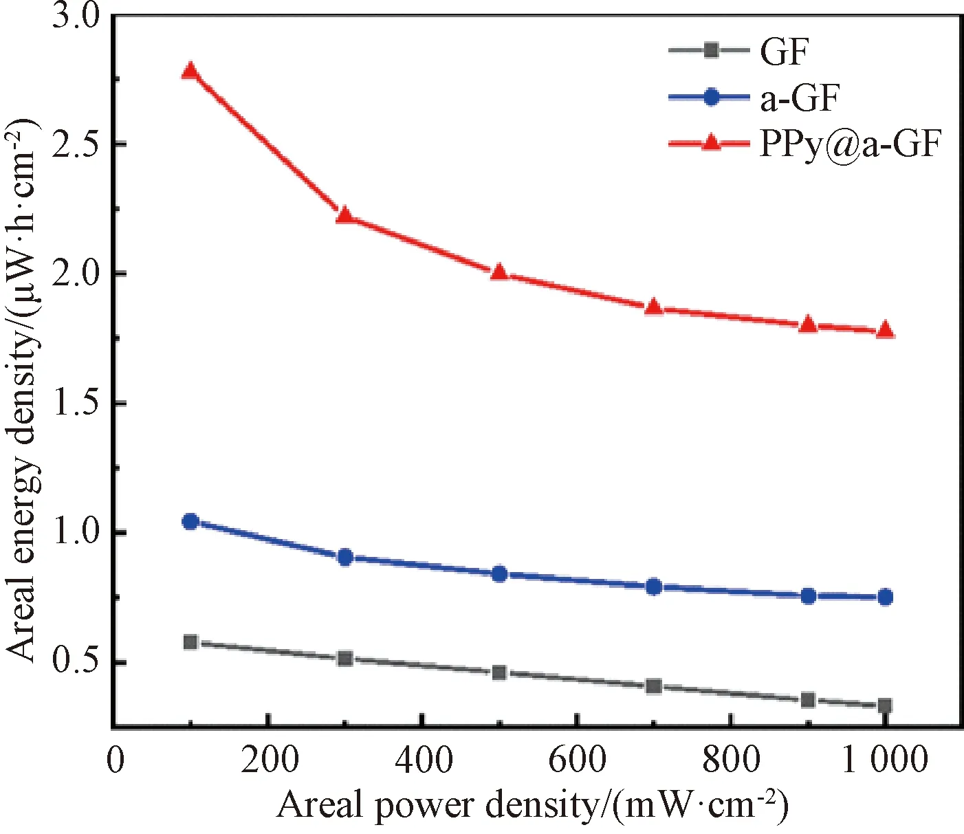
Fig.8 Areal energy densities of GF, a-GF and PPy@a-GF electrodes at different areal power densities
The cycling stability of PPy@a-GF-based FSSCs is obtained through continuous GCD measurement at a current density of 0.1 mA·cm-2, as shown in Fig.9. The capacitance retention rate of PPy@a-GF electrodes is 95% after 5 000 charge/discharge cycles. It is noted that the cycle life of PPy@a-GF electrodes decreases rapidly at the first 500 cycles. The reason is that the expansion/contraction of PPy’s molecular chains on fiber surface occurs in the initial charge/discharge process, which results in the disruption of PPy’s molecular chain[20]. Moreover, the interconnected pathway of the pores within the fiber electrode is destructed, which hinders the charge transfer and lowers the specific capacitance of the electrode[21]. After 500 cycles, the capacitance retention rate remains stable possibly due to the stabilized fiber structure.
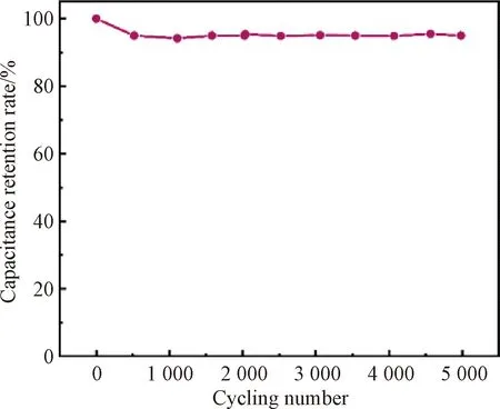
Fig.9 Capacitance retention rate of PPy@a-GF-based FSSCs after 5 000 cycles
3 Conclusions
We have successfully prepared porous wet-spun graphene-based fiber electrodes with good electrical conductivity by sequential KOH activation and PPy coating. The KOH activation aids the formation of the porous structure on GFs for the enhancement of the fiber’s SSA. PPy on activated fiber surface compensates the reduced fiber electrical conductivity after activation. Therefore, the electrical conductivity of PPy@a-GFs is 128.25 S·cm-1which is about 1.14 times as that of GFs, and the areal specific capacitance of PPy@a-GF electrodes reaches 31.25 mF·cm-2which is about 4.81 times as that of GF electrodes. Moreover, PPy@a-GF-based FSSCs display good cycling stability with a capacitance retention rate of 95% after 5 000 charge/discharge cycles.
 Journal of Donghua University(English Edition)2023年2期
- Journal of Donghua University(English Edition)的其它文章
- Simultaneous Morphologies and Luminescence Control of NaYF4∶Yb/Er Nanophosphors by Surfactants for Cancer Cell Imaging
- Fabrication of High-Efficiency Polyvinyl Alcohol Nanofiber Membranes for Air Filtration Based on Principle of Stable Electrospinning
- Construction of Oriented Structure in Inner Surface of Small-Diameter Artificial Blood Vessels: A Review
- Auto-Generation Method of Child Basic Block Structure
- Small Amplicons Mutation Library for Vaccine Screening by Error-Prone Polymerase Chain Reaction
- Proportion Integration Differentiation (PID) Control Strategy of Belt Sander Based on Fuzzy Algorithm