
SIMULATIONS OF FLOW INDUCED CORROSION IN API DRILLPIPE CONNECTOR*
2011-05-08 05:55ZHUHongjunLINYuanhuaZENGDezhiYANRentian
水動力學研究與進展 B輯 2011年6期
ZHU Hong-jun, LIN Yuan-hua, ZENG De-zhi, YAN Ren-tian
State Key Laboratory of Oil and Gas Reservoir Geology and Exploitation, Southwest Petroleum University, Chengdu 610500, China, E-mail: ticky863@126.com
SIMULATIONS OF FLOW INDUCED CORROSION IN API DRILLPIPE CONNECTOR*
ZHU Hong-jun, LIN Yuan-hua, ZENG De-zhi, YAN Ren-tian
State Key Laboratory of Oil and Gas Reservoir Geology and Exploitation, Southwest Petroleum University, Chengdu 610500, China, E-mail: ticky863@126.com
(Received June 9, 2011, Revised July 6, 2011)
Drillpipe failure is an outstanding issue in drilling engineering, often involving great financial losses. In view of the special features of the flow channel in the high failure zone, this article analyzes the drillpipe failure mechanism from the point of view of flow induced corrosion. Based on the Eulerian-Langrangian method and the discrete phase model, a numerical simulation method is used to investigate the flows of the drilling fluid in the drillpipe connector during the operation of three typical drilling methods (mud drilling, air drilling and foam drilling). From the flow field in the drillpipe connector, especially, the velocity and pressure distributions in the threaded nipple and the thickened intermediate belt, one may detect the existence of the flow induced corrosion. Then, some structural optimization measures for the drillpipe connector are proposed, and the optimization effects are compared.
flow induced corrosion, complex multiphase flow, drillpipe connector, threaded nipple, eddy current
Introduction
The drillpipe is an important part of the drill string system, which not only is used for torque transmission, but also provides the circulation channel for the drilling fluid. Besides being subjected to a combined load of tension, compression, bending and twisting, the drillpipe is eroded by the drilling fluid. Under this adverse working condition, therefore, the drillpipe is the weakest link of drilling equipments and tools.
Recently, annual economic losses of wells caused by drillpipe failure in western Africa are estimated up to 2×10⁶dollars. The remedial measures for drillpipe failure would cost as much as 1.14×10¹¹dollars in the United States every year[1], which is equivalent to 5%-10% of the national GDP. In China, about six hundred cases of drillpipe failure occur each year in oil and gas fields and several billion yuan are spent for replacing drillpipes. In addition to the great financial losses, drillpipe failure may cause blowout, a potential danger for loss of lives. Therefore, a comprehensive analysis of drillpipe failure is highly desirable to find out the main mechanisms and improved measures.
Drillpipe failure mainly occurs in the threaded nipple and the thickened intermediate belt. Taking Tarim oil field for example[2], in the 22 months from 2001 to 2003, the puncture of Φ127 drillpipe occurs 89 times in 21 wells, in which 90% take place in the pin thread[3]. For Pinghu oil field, drillpipe punctures are basically located in the thread and the thickened intermediate belt, generally in a rectangular windowlike appearance with an area about 0.02 m×0.01 m[4], as shown in Fig.1.
The effect of the flowing fluid on the drillpipe is generally ignored in previous studies. However, in the threaded nipple and the thickened intermediate belt, there will be a sudden change of the flow field due to the variation of the flow channel sections. The eddy flow formed in the threaded nipple may even lead to cavitation[5], aggravating the flow erosion. Therefore, it is necessary to analyze the drillpipe failure mechanism from the perspective of the flow induced corrosion[6-9].
Wharton studied the influence of flow conditions on the corrosion of AISI 304L stainless steel[10], whichshows that the meta-stable pitting is evident under all flow regimes and the fluid flow has an overall effect on the corrosion. Takahashi et al.[11]showed that a steam flowing at high velocities can cause erosion corrosion of pipes and give rise to wall thinning, especially in pipe elbows. The multiphase flow induced erosion corrosion in pipes was found mainly related with the interactions between the pipe surface and the fluid traveling along the surface[12-14]. The Discrete Phase Model (DPM) approach[15,16], for multiphase flow, was shown to be a good method to determine the corrosion rate.
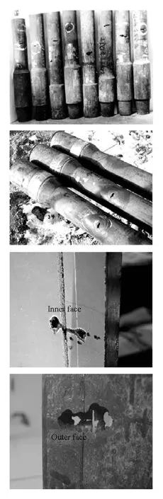
Fig.1 Macro morphology of piercing-caused leakage of thickened intermediate belt
This article, based on the multiphase fluid dynamics and the discrete phase model, proposes a numerical model of the flow field inside and outside the drillpipe connector, to simulate the flows of drilling fluid in the drillpipe connector during the operations of three typical drilling methods. The velocity and pressure distributions in the threaded nipple and the thickened intermediate belt are obtained, and the existence of the flow induced corrosion is confirmed. Then, structural optimization measures for the drillpipe connector are proposed, and their effects are verified by a comparative study.
1. Numerical computation method
1.1 Governing equations
The fluids inside and outside the drillpipe have different features. A non-Newtonian liquid flow is inside the drillpipe during the conventional mud drilling, while a liquid-solid two-phase flow is outside the drillpipe. A compressed air flow is inside the drillpipe during the air drilling, while a gas-solid two-phase flow flow is outside the drillpipe. A gas-liquid twophase flow is inside the drillpipe during the foam drilling, while a gas-liquid-solid three-phase flow is outside the drllpipe. Therefore, multiphase flows are inside and outside the drillpipe during the operation of the three drilling methods. Taking the solid particles as a discrete phase, we use the Eulerian-Lagrangian method to describe the flowing fluid, governed by the following continuity equation and the momentum equation.
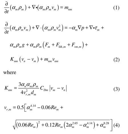
in which the subscripts m and n denote two different phases, α is the volume fraction, ρ is the density, v is the velocity, m is the mass transfer rate from one phase to another phase, t is the flowing time, p is the pressure, τ is the pressurestrain tensor, g is the gravitational acceleration, F is the body force per unit mass, Fliftis the lift force per unit mass, Fvmis the virtual mass force per unit mass, CDis the drag coefficient, vris the end speed and Re is the Reynolds number.
The turbulent flow would be inside and outside the drillpipe due to the high velocity. So the realizable k?ε turbulence model is used to close the flow governing equations and describe the turbulent properties.
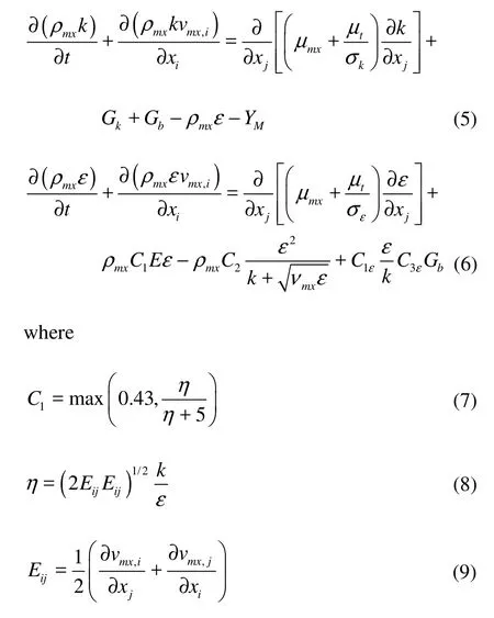
in which the subscript mx denotes the mixture, the subscripts i and j denote the coordinate directions, k is the turbulent kinetic energy per unit mass, ε is the turbulent kinetic energy dissipation rate per unit mass, μ is the dynamic viscosity, Gkis the production term of the turbulent kinetic energy due to the average velocity gradient, Gbis the production term of the turbulent kinetic energy due to the lift, YMis the impact of the compressible turbulence inflation on the total dissipation rate, E is the time-averaged strain rate, C1and η are constants determined by Eq.(7) and Eq.(8), C1ε, C3εand C2are empirical constants taken as 1.44, 0.09 and 1.9, respectively, kσ andεσ are the Prandtl numbers corresponding to the turbulent kinetic energy and the turbulent kinetic energy dissipation rate, taken as 1.0 and 1.2, respectively.
The flow parameters such as the velocity and the pressure can be obtained by solving the above equations. After the mainstream flow field is obtained, the turbulent properties of the solid particles (cuttings) are described by the particle motion equation and the turbulence equation, especially, the size of cuttings, the migration time and the velocity perturbation due to the eddy current. Then we can get the trajectory of cuttings, the attack angle and the impact intensity of cuttings on the drillpipe wall[17]. Finally, the erosioncorrosion equation can be used to get the material loss rate[18]. The particle motion equation and the erosioncorrosion equation are as follows: i
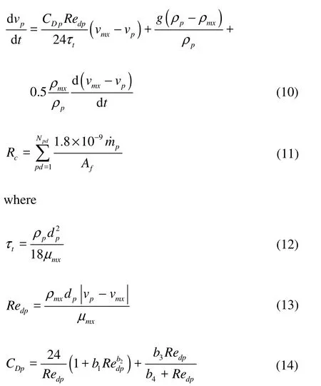
n which the subscript p denotes the discrete phase (solid particle),tτ is the particle relaxation time, dpis the particle diameter, Npdis the number of particles, Redpis the particle equivalent Reynolds number, m˙pis the mass rate of particles, Afis the projected area of particles in the wall, b1, b2, b3and b4are functions related with the shape factor, which are 0.186, 0.653, 0.437 and 7178.741, respectively, assuming that the shape factor of spherical particles is 1.
Fig.2 Channel dimensions inside and outside of API 5indrillpipe (Unit: m)
Fig.3 Grid distribution of computational domain
In the simulation, the air is considered as the compressive gas, the foam is the water containing 20% volume fraction of N2, and the mud is a powerlaw fluid conforming to the relation τ =0.309(dv/ dy)0.737. Cuttings are added into the continuous phase flow field as a discrete phase of spherical particles.
The equations describing the drilling fluid flow are solved with a finite-volume industrial CFD code, Fluent 12.0. Additional source terms and the erosioncorrosion model are added to the flow governing equations using User-Defined Functions (UDFs). The particle phase is simulated based on the Lagrangian approach using the DPM in Fluent. The second-order upwind discretization is adopted for the momentum equation. And the SIMPLE algorithm is applied to resolve the pressure-velocity coupling.
1.2 Computational domain
The frequently used drillpipe, API 5indrillpipe, is chosen in our analysis. Its geometry is shown in Fig.2. A pipe segment of 2 m in length is adopted in each end of the connector to ensure a fully developed flow. In view of the rotation axial symmetry of the computational domain, a two-dimensional geometric model is established.
All geometry generation and meshing are performed using Gambit 2.3 mesh-generator. In order to control the grid distribution, the computational domain both inside and outside the drillpipe connector is divided into five blocks. All blocks are discretized with rectangular cells except for the central block, where is the threaded nipple and where triangular elements are adopted for a better fit of its special shape. A progressive mesh is used to discretize the flow channel-varying region, as shown in Fig.3. There is a boundary layer near the drillpipe wall with fourlayer grids (the cell height of the first layer is 0.001 m and the growth factor is 1.3). In this study, an optimal grid density is reached by repeating computations until a satisfactory independent grid is found.
1.3 Boundary conditions
In order to facilitate the comparative analysis, the velocity inlet boundary condition is used for the inlet boundaries inside and outside the drillpipe connector. And the velocity is assumed to be 4 m/s in the inlet. The pressure at the outlet takes a constant value of 0 Pa. The no-slip boundary condition is applied at the wall of the drillpipe and the casing. The outer wall of the drillpipe and the inner wall of the casing are assumed to be reflection boundaries, which means that the particles will bounce back to the mainstream after impinging the wall.
2. Results and discussions
2.1 Flow induced corrosion of API drillpipe connector Figure 4 shows the velocity distributions in the threaded nipple and inside and outside the drillpipe connector during the operation of three drilling methods. Due to the existence of the thickened intermediate belt, both the cross-sectional areas of the flow channels inside and outside the drillpipe connector narrow down, leading to an obvious increase of the velocity and a more severe flow erosion-corrosion. The high turbulence intensity near the wall during theair drilling or the foam drilling promotes the corrosion reaction of the material exchange. Especially, more severe localized corrosions will occur in the wall no longer smooth with the result of puncture of the drillpipe eventually. Relatively speaking, a greater viscosity of the mud would lead to a thicker boundary layer with smaller velocity gradient near the wall, forcing the main flow gathering to the axis. So the mud drilling can inhibit the flow erosion-corrosion to a certain extent.
The eddy current can be seen in the threaded nipple during all three drilling operations. During the air drilling and the foam drilling, not only an obvious anticlockwise main vortex could be seen in the threaded nipple, but also a second vortex in the opposite direction of the main vortex would join in. During themud drilling, however, only the anticlockwise vortex, equal to the magnitude of the second vortex during the air or foam drilling, exists in the threaded nipple.
Fig.4 Velocity distributions in the threaded nipple and inside and outside the drillpipe connector, and local zoom view of velocity contours and streamlines in the threaded nipple
The eddy current erodes the threaded nipple continuously, with a result of the premature failure of the thread. In addition, the eddy current makes the phase transition easier, giving rise to the escape of non-dissolved bubbles from the liquid, increasing the mass transfer coefficient of the corrosive component and accelerating the electrochemical reaction rate of metal surfaces[19]. And escaping bubbles gather into large bubbles or swarm bubbles, bringing about the cavitation. Therefore, measures should be taken to inhibit the occurrence of the eddy current, especially during the air or foam drilling operations.
Fig.5 Pressure distributions inside and outside the drillpipe connector
The pressure drop during the mud drilling is the largest among different drilling operations due to a larger friction loss caused by a larger viscosity (see Fig.5). The foam is a gas-liquid two-phase flow, with viscosity larger than the air. So the pressure drop during the foam drilling is the second largest. The pressure drop during the air drilling is the smallest. In both the pressure drop curves inside and outside the drillpipe connector one sees a low ebb. The pressure inside the drillpipe connector is the smallest during the air drilling. The pressure during the foam drilling is the second smallest. But during the mud drilling, the low pressure is not obvious. Outside the drillpipe connector, there is an obvious low-pressure area during the foam drilling. And a relatively smaller low-pressure area could be found during the mud drilling. But during the air drilling, the fluctuation of pressure is not significant.
When the pressure is below the saturated vapor pressure, the vaporization of the liquid will occur and bubbles will be generated. Following the mainstream, the bubbles migrate into the normal pressure area, leading to an instantaneous burst with a strong impact on the wall. Micro-pits or micro-cracks then appear in the drillpipe wall. And the rough surface will become the cradle of new bubbles, aggravating the cavitation situation. The low pressure and the pressure fluctuations in the drillpipe connector should thus be avoided as far as possible.
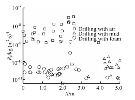
Fig.6 Erosion rate of outside surface of drillpipe connector
The most important role of the drilling fluid in the annulus is to carry cuttings. The migration of cuttings is influenced by the turbulence of the continuous phase. Cuttings impinge the wall inevitably at a certain angle, resulting in a loss of the wall material. This phenomenon is more prominent in a varying flow field. As shown in Fig.6, the erosion rate is larger in the threaded nipple and the thickened intermediate belt. During the mud drilling, the severe corrosion area locates in the front of the thickened intermediate belt. While during the air or foam drilling, this area locates in the middle of the connector and the back end of the thickened intermediate belt.
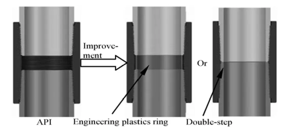
Fig.7 Structural optimization measures of drillpipe connector
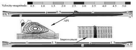
Fig.8 Comparison of velocity distribution and local zoom view of streamlines in threaded nipple before and after optimization
Relatively speaking, the erosion rate is the highest during the air drilling with a value of 7.066× 10⁻⁸kg/(m2s). Followed is that during the foam drilling. And during the mud drilling one has the smallest erosion rate. The drillpipe has a large twist during the air drilling, leading to a continuously varying flow channel. The flow field outside the drillpipe then changes continuously, exacerbating the erosion corrosion. Therefore, the impact of cuttings on the drillpipe wall during the air drilling needs even more attentions.
2.2 Structural optimization
Box and pin threads are used to connect the API drillpipes. The connector is usually thickened both inside and outside in order to ensure the strength, with a thickness of 0.0285 m, larger than that of the drillpipe. So the shape of the thickened intermediate belt should not be adjusted indiscreetly. However, there is a big gap in the thread nipple, which can be filled by engineering plastic seal ring or double-step thread (see Fig.7). The structure of the thread nipple is thus optimized by this kind of methods in this study.
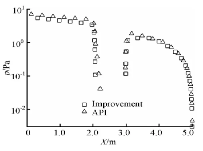
Fig.9 Comparison of pressure drop before and after optimization
The flow fields inside the drillpipe during the air drilling before and after the structural optimization are shown in Fig.8. After the thread nipple filled, the transition of the velocity distribution is smoothened in this region. And the eddy current is not obviously seen as before, weakening the fluid erosion-corrosion. It can be also seen in Fig.9, that the smallest pressure in the thread nipple increases after the structural optimization, reducing the damage of cavitation. We may thus conclude that the flow induced corrosion can be suppressed by smoothening the inner wall of the drillpipe connector to increase the service life of the drillpipe.
3. Conclusions
(1) An analysis of the drillpipe failure mechanism is made from the point of view of the flow induced corrosion in this article. Complex multiphase flows of the drilling fluid in the drillpipe connector during the operation of three typical drilling methods are simulated based on the Eulerian-Langrangian method and the discrete phase model. The obtained flow field confirms the existence of the flow induced corrosion.
(2) The flow field in the API drillpipe connector indicates that the flow velocity increases with the thickening of the connector, aggravating the flow erosion. The boundary layer of the mud can inhibit the flow erosion-corrosion to a certain extent. The eddy current in the thread nipple, especially, during the air drilling and the foam drilling, erodes the threaded nipple continuously. Cavitation is caused in the same place by a low pressure. Due to the large erosion rate, the impact of cuttings on the drillpipe wall during the air drilling needs more attentions.
(3) Engineering plastic seal ring and double-step thread are proposed to fill the thread nipple. A significant reduction of the eddy current and low-pressure region is seen after taking this structural optimization measure.
Acknowledgement
This work was supported by the Fundamental Research Funds for the Southwest Petroleum University (Grant No. 2010xjz133).
References
[1] YANG Long. Study of mechanism of casing failure[D]. Ph. D. Thesis, Chengdu: Southwest Petroleum University, 2003(in Chinese).
[2] LUO Fa-qian. Failure mechanism and countermeasures of drill string in Tarim Oilfield[D]. Ph. D. Thesis, Chengdu: Southwest Petroleum University, 2006(in Chinese).
[3] LIAN Zhang-hua, LUO Fa-qian and GONG Jian-wen et al. Analysis of drill pipe washout causes in Tarim Oilfield[J]. Drilling and Production Technology, 2003, 26(6): 62-64(in Chinese).
[4] GUO Yong-feng, GUO Shi-sheng and LI Hui-liang. Research on drill pipe damaged in Pinghu field[J]. China Offshore Oil, 2004, 16(2): 107-111(in Chinese).
[5] BAI Li-xin, XU Wei-lin and LI Chao et al. The counterjet formation in an air bubble induced by the impact of shock waves[J]. Journal of Hydrodynamics, 2011, 23(5): 562-569.
[6] RANJBAR K. Effect of flow induced corrosion and erosion on failure of a tubular heat exchanger[J]. Materials and Design, 2010, 31(1): 613-619.
[7] SHEHATA A. S., NOSIER S. A. and SEDAHMED G. H. The role of mass transfer in the flow-induced corrosion of equipments employing decaying swirl flow[J]. Chemical Engineering and Processing, 2002, 41(8): 659-666.
[8] EL-SHAZLY Y. M., ZAHRAN R. R. and FARAG H. A. et al. Mass transfer in relation to flow induced corrosion of the bottom of cylindrical agitated vessels[J]. Chemical Engineering and Processing, 2004, 43(6): 745-751.
[9] ZHENG Dong-hong, CHE De-fu. An investigation on near wall transport characteristics in an adiabatic upward gas-liquid two-phase slug flow[J]. Heat and Mass Transfer, 2007, 43(10): 1019-1036.
[10] WHARTON J. A., WOOD R. J. K. Influence of flow conditions on the corrosion of AISI 304L stainless steel[J]. Wear, 2004, 256(5): 525-536.
[11] TAKAHASHI K., TSUNOI S. and HARA T. et al. Experimental study of low-cycle fatigue of pipe elbows with local wall thinning and life estimation using finite element analysis[J]. International Journal of Pressure Vessels and Piping, 2010, 87(5): 211-219.
[12] TANG Ping, YANG Jian and ZHENG Jin-Yang et al. Failure analysis and prediction of pipes due to the interaction between multiphase flow and structure[J]. Engineering Failure Analysis, 2009, 16(5): 1749-1756.
[13] CHENG Wen, HU Bao-wei and YANG Chun-di et al. The velocity field of multiphase flow and efficiency of biological aeration filter[J]. Journal of Hydrodynamics, 2010, 22(2): 260-264.
[14] ZHENG Jin-hai, SOE Mee Mee and ZHANG Chi et al. Numerical wave flume with improved smoothed particle hydrodynamics[J]. Journal of Hydrodynamics, 2010, 22(6): 773-781.
[15] LIN J. Z., SHEN L. P. and ZHOU Z. X. The effect of coherent vortex structure in the particulate two-phase boundary layer on erosion[J]. Wear, 2000, 241(1): 10-16.
[16] ALFONSO C. A., ARMANDO G. M. and ROMERO C. A. et al. Numerical investigation of the solid particle erosion rate in a steam turbine nozzle[J]. Applied Thermal Engineering, 2007, 27(14): 2394-2403.
[17] DICKENSON J. A., SANSALONED J. J. Discrete phase model representation of Particulate Matter (PM) for simulating PM separation by hydrodynamic unit operations[J]. Environmental Science and Technology, 2009, 43(21): 8220-8226.
[18] THINGLAS T., KAUSHAL D. R. Comparison of twoand three-dimensional modeling of invert trap for sewer solid management[J]. Particuology, 2008, 6(3): 176-184.
[19] HU Xin-ming, NEVILLE A. CO2erosion-corrosion of pipeline steel (API X65) in oil and gas conditions–A systematic approach[J]. Wear, 2009, 267(11): 2027-2032.
10.1016/S1001-6058(10)60177-1
* Project supported by the National Nature Science Foundation of China (Grant No. 51074135).
Biography: ZHU Hong-jun (1983-), Male, Ph. D. Candidate, Lecturer

- 水動力學研究與進展 B輯的其它文章
- LATTICE BOLTZMANN METHOD SIMULATIONS FOR MULTIPHASE FLUIDS WITH REDICH-KWONG EQUATION OF STATE*
- NUMERICAL SIMULATION OF HYDRODYNAMIC CHARACTERISTICS ON AN ARC CROWN WALL USING VOLUME OF FLUID METHOD BASED ON BFC*
- DYNAMIC ANALYSIS OF FLUID–STRUCTURE INTERACTION OF ENDOLYMPH AND CUPULA IN THE LATERAL SEMICIRCULAR CANAL OF INNER EAR*
- NUMERICAL SIMULATION OF FLOW OVER TWO SIDE-BY-SIDE CIRCULAR CYLINDERS*
- NUMERICAL STUDY OF HYDRODYNAMICS OF MULTIPLE TANDEM JETS IN CROSS FLOW*
- EXPERIMENTAL STUDY ON SEDIMENT RESUSPENSION IN TAIHU LAKE UNDER DIFFERENT HYDRODYNAMIC DISTURBANCES*