
NUMERICAL SIMULATION OF FLOW OVER TWO SIDE-BY-SIDE CIRCULAR CYLINDERS*
2011-05-08 05:55SARVGHADMOGHADDAMHesamNOOREDINNavid
水動力學研究與進展 B輯 2011年6期
SARVGHAD-MOGHADDAM Hesam, NOOREDIN Navid
Department of Mechanical Engineering, Neyshabur Branch, Islamic Azad University, Neyshabur, Iran, E-mail: hesamsarvghad@gmail.com
GHADIRI-DEHKORDI Behzad
Department of Mechanical Engineering, School of Engineering, Tarbiat Modares University, Tehran, Iran
NUMERICAL SIMULATION OF FLOW OVER TWO SIDE-BY-SIDE CIRCULAR CYLINDERS*
SARVGHAD-MOGHADDAM Hesam, NOOREDIN Navid
Department of Mechanical Engineering, Neyshabur Branch, Islamic Azad University, Neyshabur, Iran, E-mail: hesamsarvghad@gmail.com
GHADIRI-DEHKORDI Behzad
Department of Mechanical Engineering, School of Engineering, Tarbiat Modares University, Tehran, Iran
(Received March 21, 2011, Revised May 20, 2011)
In the present paper, the unsteady, viscous, incompressible and 2-D flow around two side-by-side circular cylinders was simulated using a Cartesian-staggered grid finite volume based method. A great-source term technique was employed to identify the solid bodies (cylinders) located in the flow field and boundary conditions were enforced by applying the ghost-cell technique. Finally, the characteristics of the flow around two side-by-side cylinders were comprehensively obtained through several computational simulations. The computational simulations were performed for different transverse gap ratios (1.5 ≤ T/ D ≤ 4) in laminar ( Re =100,200) and turbulent ( Re =104) regimes, where T and D are the distance between the centers of cylinders and the diameter of cylinders, respectively. The Reynolds number is based on the diameter of cylinders, D. The pressure field and vorticity distributions along with the associated streamlines and the time histories of hydrodynamic forces were also calculated and analyzed for different gap ratios. Generally, different flow patterns were observed as the gap ratio and Reynolds number varied. Accordingly, the hydrodynamic forces showed irregular variations for small gaps while they took a regular pattern at higher spacing ratios.
side-by-side cylinders, vortex shedding, flow induced forces, finite volume method, turbulent flow
Introduction
Flow past a group of circular cylinders in different arrangements plays an important role in various engineering applications and it has been the subject of many researches for decades[1]. Among these arrangements, two-cylinder configurations have shown to be more effective in different areas such as flow past heat exchanger tubes, transmission cables, offshore platforms and chimney stacks. Furthermore, study of flow past two circular cylinders provides a broad perspective toward understanding the complex behavior of different arrangements. With respect to cross-flow, the configuration of two circular cylinders is divided to tandem, side-by-side and staggered arrangements. This complexity arises due to interaction of shed vortices from the two cylinders in close proximity,
However, in an experimental work on two sideby-side cylinders at Reynolds numbers (Re) ranging from 50 to 200, Williamson[3]realized harmonic modes of vortex shedding behind the cylinders and observed the in-phase or anti-phase synchronization of wakes for specific gaps between cylinders. He observed a bistable biased flow pattern for critical spacing (1.1 ≤ T/ D ≤ 2.2), i.e., narrow and wide wakes flipflopped randomly behind each cylinder as time advanced. For gaps larger than 2.2D, he observed two distinct wakes that were generally in-phase but as the gap increased to over 5D, the flow around two cylinders behaved like the case of a single fixed cylinder.
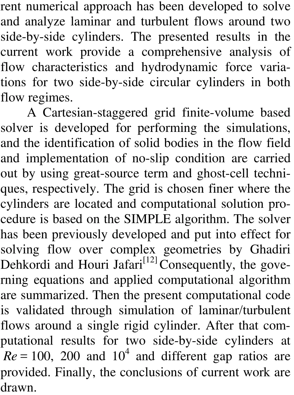
1. Computational approach to the problem
1.1 Equations of the problem
The differential equations governing incompressible, viscous, unsteady and 2-D fluid flow comprise the continuity and momentum equations which are written as follows:
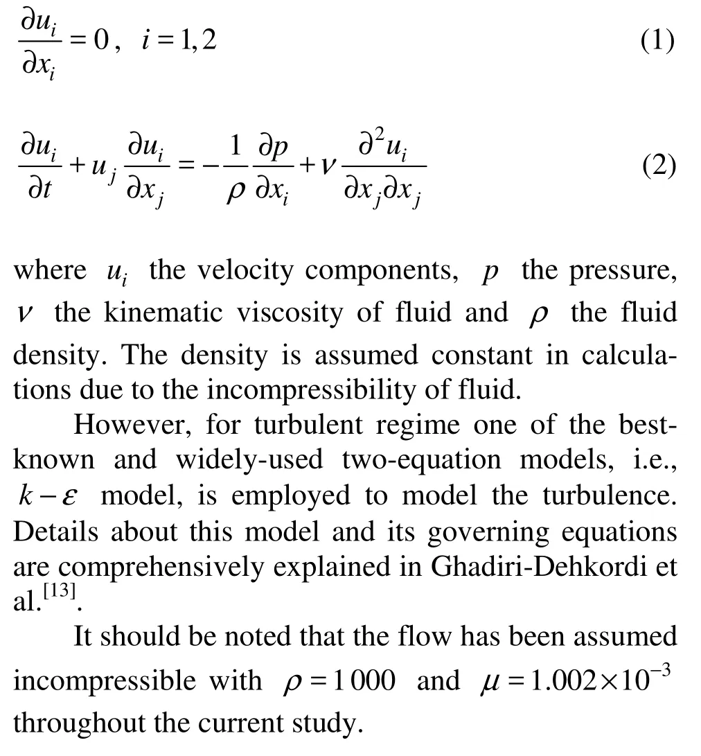
1.2 Problem limits
A 40D×30D rectangular domain is provided for locating two equal-sized circular cylinders in sideby-side arrangement. The centers of both cylinders are located at 10D from the inlet boundary, 30D from the outlet boundary and 13D-14D from upper and lower boundaries, where D denotes the cylinder diameter and has been chosen equal to 0.04. Flow enters from the left side of the field with the velocity of U and coordinates of cylinders’ centers have been set at (10D,10D) .The computational domain for side-byside arrangement is shown in Fig.1 where T is the transverse gap spacing between two cylinders.
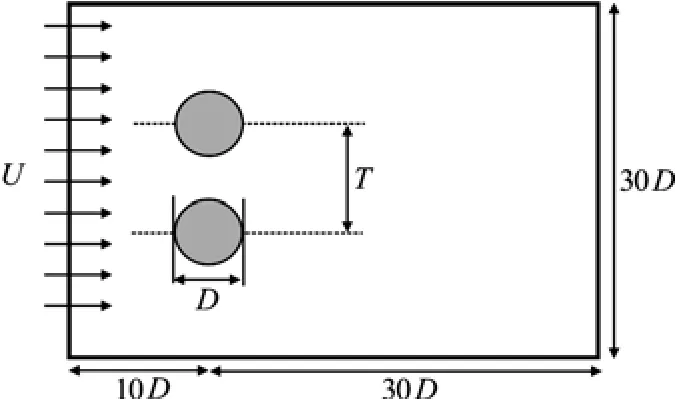
Fig.1 Computational domain for two side-by-side cylinders
At the inlet of the flow field, the Dirichlet boundary conditions are applied (u=U,v=0,k= 0.03U2and ε= k2/0.005l, where U is the freestream velocity, and l is the length of computational domain) and at the outlet, the Neumann-type conditions are employed ( ? u/? x =0, ?v /?x =0, ?k/? x=0 and ?ε /?x =0).
However, regarding the enforcement of no-slip condition on the curved boundaries of cylinders, in this study this condition is applied using the ghost-cell method. This method which has been described in detail by Ghadiri Dehkordi and Houri Jafari[12], offers an outstanding solution for the problem of fitting curved boundaries of the cylinders onto the grid points inside a Cartesian grid. Accordingly, to assign values to velocity components, the great-source term technique described by Ghadiri Dehkordi and Houri Jafari[12], is employed.
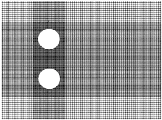
Fig.2 A close view of generated mesh for two side-by-side cylinders
2. Grid generation and discretization of the equations
In the current work, the grid generation in the flow field is done through a non-uniform Cartesianstaggered grid in order to implement the present computational code. In this grid, as is shown in Fig.2, the enclosed area of two cylinders is refined with respect to other areas of the flow field. A grid distribution of 210×210 cells is selected for the computations around the circumference of cylinders. To show the independency of results from the grid size, the verification of mesh independency was done for different grid sizes. The results are described in detail in Ghadiri-Dehkordi et al.[13]. According to this verification, for grids finer than 210×210 cells, no significant change was observed and there was just a 0.07% difference between this grid structure and 190×190 grid. So the solution is sufficiently grid independent and hereinafter other simulations of the paper are carried out by using the 210×210 cells grid.
Moreover, the pressure, kinetic energy and dissipation rate of turbulence (p,k and ε) are calculated for main grid points, while u and v velocity components are calculated for the points located on the staggered control volume surface.
The discretization of governing equations is carried out using the finite-volume method, where a fully implicit approach is applied for temporal discretization of equations and space discretization is performed using a hybrid scheme. The general forms of discretized equations including momentum, pressure and velocity correction equations are presented in detail in Patankar[14]for reference, and hence, they are not mentioned again in here.
3. Solution procedure
Finally, the solution procedure of current study is based on the SIMPLE computational algorithm[14]. Main steps of SIMPLE algorithm is summarized as follows: guess of pressure field, solution of momentum equations, calculation of the total residual (b), pressure and velocity correction, solution of other differential equations for φ (equations of k and ε) and iteration of all steps until the full convergence (b≈0.0) is reached. This residual includes the residuals of momentum and k, ε equations and pressure correction residual from continuity equation. Hence, choosing a very small value, 10–6in this paper, seems appropriate and adequate. As a matter of fact, this value represents the intrinsic error of discretization which is unavoidable. Considering the present approach for discretization of governing equations, lower values than this would have no significant effect on the accuracy of our solution.
4. Validation of the solver
Analysis of shedding process and flow behavior behind a single cylinder would greatly help to understand the flow characteristics between two side-byside cylinders. On the other hand, this benchmark has been investigated by many researchers both experimentally and numerically and is a proper case for validation of the solver.In this section, the current numerical approach and employed computational code are validated through simulation of flow around a fixed circular cylinder at Re=100 (laminar case) and the results are compared with other experimental and numerical works in Table 1. The comparison of results for the turbulent case is provided in Ghadiri-Dehkordi et al.[13]. The lift and drag coefficients and the Strouhal number are defined as follows:
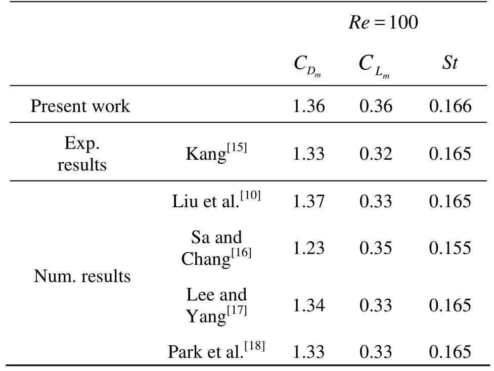
Table 1 Comparison of mean drag coefficient,CDm, maximum lift coefficient, CLmand Strouhal number, St, for a single cylinder at Re=100
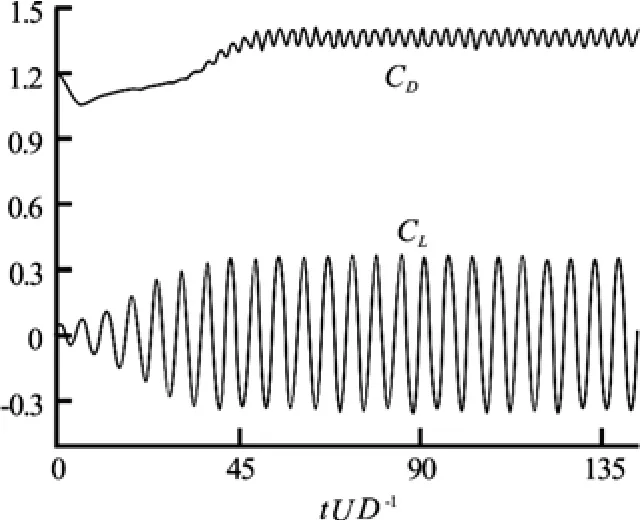
Fig.3 Time histories of lift and drag coefficients for the flow past a stationary cylinder at Re=100
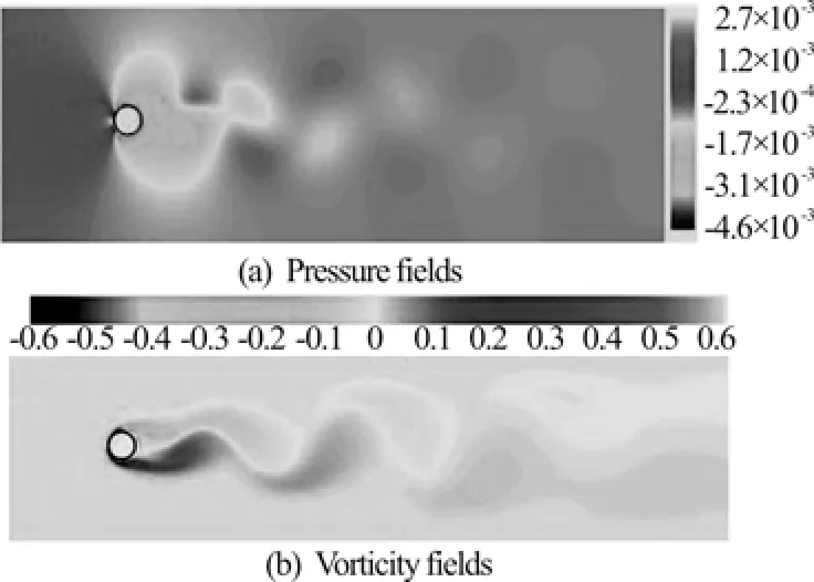
Fig.4 Flow characteristics around a single stationary cylinder at Re =100 and tU/D=77
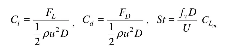
where FLand FDdenote lift and drag forces, respectively. St is the Strouhal number, D is the cylinder diameter, and fvis the frequency of vortex shedding, which can be calculated from the oscillation frequency of lift force.
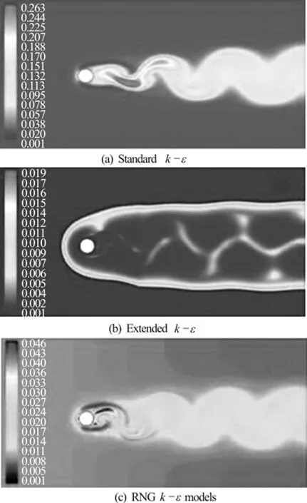
Fig.5 Effective viscosity distribution for flow around a fixed circular cylinder at Re =104and tU/D =87
The simulation results of flow past a stationary cylinder are presented for mean drag coefficients, maximum lift coefficient and Strouhal numbers and are compared with the data in literature in Table 1. Non-dimensional time step has been set to 0.004. From Table 1, we can see that at Re=100 the resu-lts of the present work agree closely with other results. Time histories of lift and drag coefficients for this Reynolds number are shown in Fig.3, which is followed by pressure and vorticity contours for the mentioned Reynolds number in Fig.4. As it is evident, vortices are shed periodically from the cylinder and a vortex street is formed at these Reynolds numbers. The lift and drag coefficients also oscillate due to the asymmetric pressure distribution occurred by periodic vortex shedding.
Finally, effective viscosity distribution in the flow field around a fixed circular cylinder is calculated by all three different RANS models at Re=104and the results are depicted in Fig.5. As it can be seen from this figure, the effective viscosity distribution simulated by the extended and RNG k?ε models show lower values with respect to the standard k?ε model, which implies that this case has a lower shedding. The separation region is also greater than that obtained with the standard model and is closer to experimental conditions. Due to this large separation region around a single cylinder and considering the features of mentioned models, this result is predictable. The prediction of larger separation region with modified models offers a greater pressure drop, which leads to an increased pressure lift coefficient. Hence, the drag coefficients calculated by modified models are greater than those of the standard model and are relatively close to experimental results presented by Ghadiri-Dehkordi et al.[13]. In this case, the most comparative value of drag coefficient and the best simulation of effective viscosity distribution in accordance with the exact method of DNS are obtained by RNG model. Therefore, this model is employed for simulating the turbulent flow around two side-by-side cylinders.
5. Flow over two side-by-side cylinders
The study of flow around a fixed cylinder presented in previous section provides a good insight into better understanding the flow characteristics around two-cylinder geometries. In this section, the results for the simulation of flow around two side-by-side circular cylinders are analyzed and comparison of these results with other data are presented to reveal the effect of different flow parameters on the flow pattern. It will be seen that the variation of the Reynolds number and transverse gap have significant effects on flow characteristics behind upper and lower cylinders. These changes lead to a notable deviation from the results obtained for a fixed cylinder in terms of hydrodynamic forces, wake pattern and vortex shedding from both cylinders.
Accordingly, first the laminar flows around two side-by-side cylinders are comprehensively studied and then it is followed by the results of turbulent regime where the flow shows different behaviors due to high Reynolds number.
5.1 Laminar flow, Re=100
In this section laminar flows around two side-byside cylinders at Re=100 and gap ratios of T/ D= 1.5, 3 and 4 are simulated and temporal variation of hydrodynamic forces along with pressure and vorticity contours and streamlines are presented for each case.
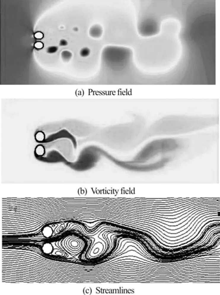
Fig.6 Flow characteristics for two side-by-side cylinders at Re =100 t/D=1.5 and tU/D=65
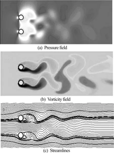
Fig.7 Flow characteristics for two side-by-side cylinders at Re =100 t/D=3 and tU/D=65
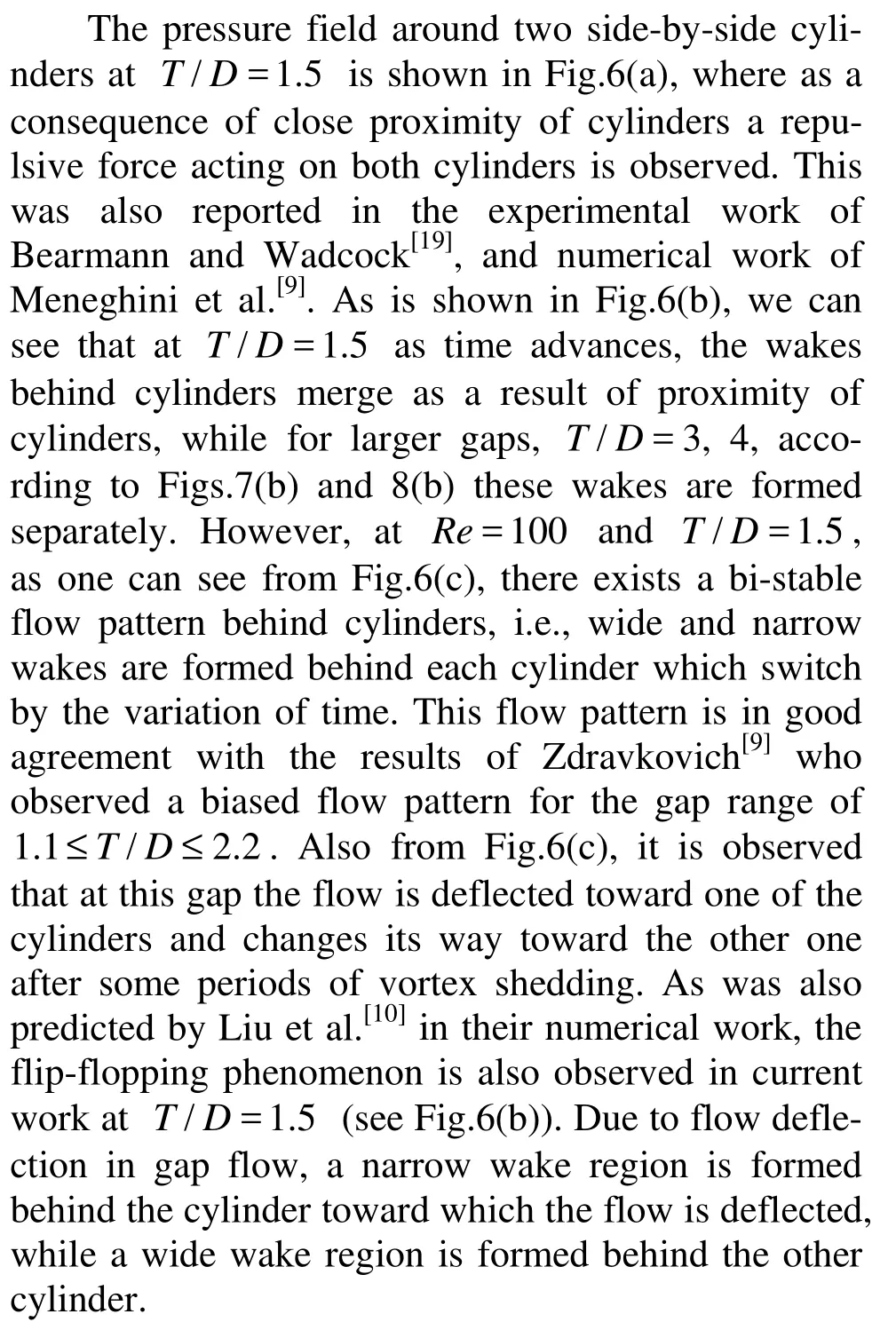
Fig.8 Flow characteristics for two side-by-side cylinders at Re =100 T/D=4 and tU/D=65
Nevertheless, by increasing the transverse gap to T/ D =3, it can be seen from Figs.7(a)-7(c) that flow characteristics show different behaviors due to the change of gap. Figure 7(a) presents the pressure contours for this case. Figure 7(b) shows the asymmetric shedding of synchronized in-phase vortices. As time advances, a longer wake is formed in the vertical direction due to the merging of these vortices which stops at a distance downstream the cylinders. It can be seen from Figa.7(b), and 7(c) that unsteady flows around upper and lower cylinders separate from the surface of cylinders at counterpart points. As is shown in Fig.7(c), streamlines in the wakes of both cylinders follow an in-phase asymmetric pattern. Also, separation points of both cylinders occur near the right side of the base of each cylinder.
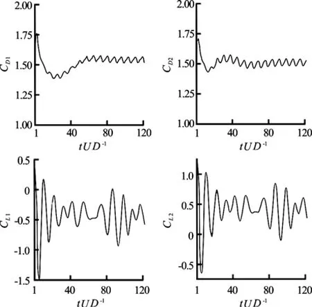
Fig.9 Time histories of lift and drag forces for Re=100 and T/D=1.5
Time histories of lift and drag forces for different gap ratios at Re=100 are depicted in Figs.9 through 11. From these figures, we can clearly see that by decreasing the gap both cylinders experience higher values of lift forces. However, as the gap decreases the velocity of gap flow increases and therefore a more significant difference is predicted in the timeaveraged variations of lift forces at lower gap ratios. The lift and drag coefficients vary irregularly with time at T/ D =1.5 which implies that the flow is unsteady and non-periodic, as shown in Fig.9. As Zhouet al.[22]and Xu et al.[23]reported in their experimental work, gap flow deflects to the cylinder with higher frequency which leads to a higher drag coefficient for this cylinder. This was also observed in our paper and is shown in Fig.9. Also from this figure, we can clearly see that time varying drag coefficients at this gap change out of phase and as a result of random flip-flop of wakes behind cylinders in the direction of gap flow, both cylinders irregularly experience higher drag coefficients. Figure 9 shows that at this gap, the upper cylinder experiences a positive lift coefficient while this coefficient takes negative values for the lower cylinder. This is justified by noting that the transverse gap between cylinders inhibits the evolution of flow and consequently a high-pressure region is developed in the separation distance. On the other hand, due to higher shedding frequency for lower cylinder, it experiences higher drag values than does the upper cylinder. Accordingly, the flow deflects from lower cylinder to the upper one. As a consequence of this deflection, time-averaged variations of lift will be different for each of these cylinders.
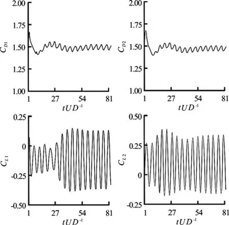
Fig.10 Time histories of lift and drag forces for Re=100 and T/D=3
In Fig.10, the time histories of hydrodynamic forces for T/ D =3 are shown. From this figure we can observe that drag coefficient variations at this gap are similar but out of phase, the oscillation amplitudes of this force follow a similar trend but they have different values. Comparing Figs. 9 and 10, we can see that the difference in oscillation amplitudes for both cylinders at T/ D =3 is lower than those at T/ D =1.5, which is because of the diminishment of interference effects due to the increase of gap distance. From Fig.10, we can also observe that lift coefficients at this gap are in anti-phase with respect to each other but they approach an in-phase trend after some periods of vortex shedding. Synchronized variations of lift and drag coefficients (see Fig.10) corroborate the periodic behavior of vortex shedding from both cylinders at this gap.
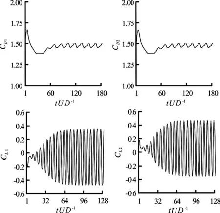
Fig.11 Time histories of lift and drag forces for Re =100 and T/D=4
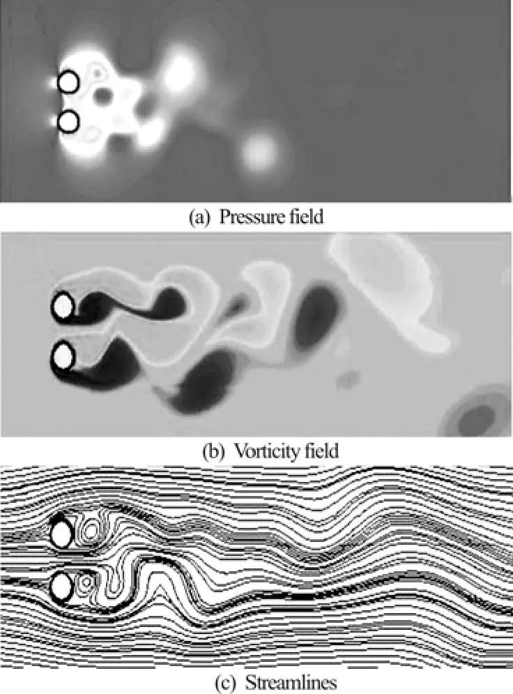
Fig.12 Flow characteristics for two side-by-side cylinders at Re =200, T/D=2 and tU/D=65
Finally, at T/ D =4 the synchronized variation of hydrodynamic forces with time confirms the synchronized vortex shedding from both cylinders, as we can see i n F ig.1 1. Simil ar to the o bserv atio ns at T/ D =3,wecanobservefromFig.11thatthemeandrag coefficient is the same for both cylinders at this gap. The oscillation amplitudes of lift forces differ slightly from the previous case (T/ D =3), except that due t o more inc reas e in gapspacing , interferen ce effectdiminishesandthereforealowerdifferencein oscillation amplitudes of lift coefficients is observed.
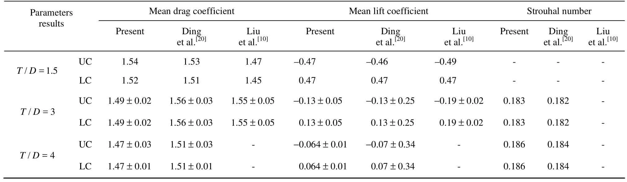
Table 2 Comparison of flow parameters for two side-by-side cylinders at Re=100
A comparison of different flow parameters at Re =100 and different gaps with other numerical and experimental results is provided in Table 2.
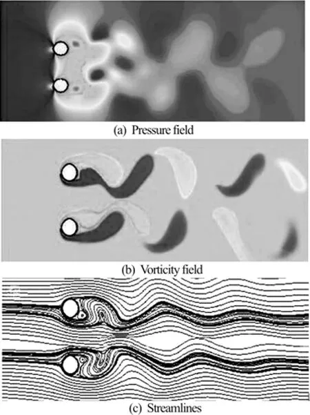
Fig.13 Flow characteristics for two side-by-side cylinders at Re =200, T/D=3 and tU/D =65
5.2 laminar flow, Re=200
It is shown in current work that interference effects and flow pattern around two side-by-side cylinders are sensitive to the Reynolds number and gap spacing, with the latter having a stronger effect. The effect of increase in the Reynolds number is verified in more detail for Re =200 in this section. The pressure and vorticity contours and strea- mlines for different gaps at Re =200 are shown in
It was mentioned before that for this gap, the biased flow pattern is bi-stable, i.e., narrow and wide wakes behind both cylinders as well as the direction of gap flow switch by time from one cylinder to the other. Wake patterns behind these cylinders do not show a synchronized behavior at this spacing.
As the gap spacing increases to T/ D =2, the characteristics of flow show a slight difference due to the decrease of interference effect. From the pressure and vorticity contours given in Figs.12(a) and 12(b) respectively, we can observe that despite the diminishment of repulsive force between cylinders, the wake still holds the pattern of a single cylinder. The wake does not follow a regular pattern and flip-flopping phenomenon still exists. Regarding the suction pressure around lower cylinder, it can be seen from Fig.12(b) that vortex shedding from this cylinder is stronger than the one from the upper cylinder. Thestreamlines for this case, as shown in Fig.12(c), follow a similar pattern as the ones at T/ D =1.5 where for the present case the gap flow deflects toward the lower cylinder. Studying the presented contours reveals a close similarity between current flow pattern with the one at T/ D =1.5, except that unlike previous case the vortices are merged nearly outside the separation distance at T/ D =2.
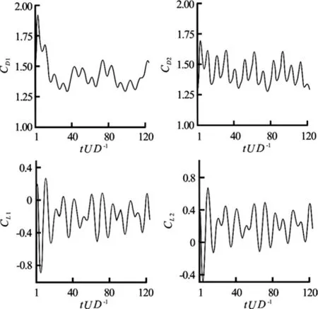
Fig.14 Time histories of lift and drag forces for Re =200 and T/D=2
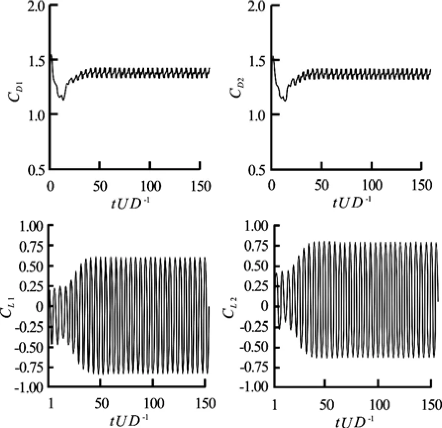
Fig.15 Time histories of lift and drag forces for Re =200 and T/D=3
However, at T/ D =3 the flow pattern is different from the patterns observed for the two previous gaps. Due to the increase of the Reynolds number, at this gap pressure is distributed differently in comparison to the same gap at Re=100, as shown in Fig.13(a). The flip-flopping pattern no longer exists and as shown in Fig.13(b) a synchronized anti-phase flow pattern is observed behind both cylinders, vortices are not merged and begin to shed separately as a single vortex street. From Fig.13(c), the symmetry of flow field with respect to the gap spacing between cylinders can be observed. Comparing the flow behaviors for the counterpart gaps at this Reynolds number, we can clearly see the effect of the Reynolds number on flow characteristics. On the other hand, the presented contours and streamlines confirm that the unsteady flow around two cylinders shows more sensitivity to the change of separation distance. Consequently, an asymmetric wake pattern is observed behind each cylinder at this gap, as shown in Fig.13(b).
Finally, at T/ D =4 the flow shows similar behavior to the previous case. However, the repulsive force between the cylinders is completely diminished and a fully periodic vortex shedding is observed from both cylinders. The flow pattern becomes more symmetric than before because interference effects decrease significantly as the gap increases. The asymmetric wakes behind upper and lower cylinders are in anti-phase.
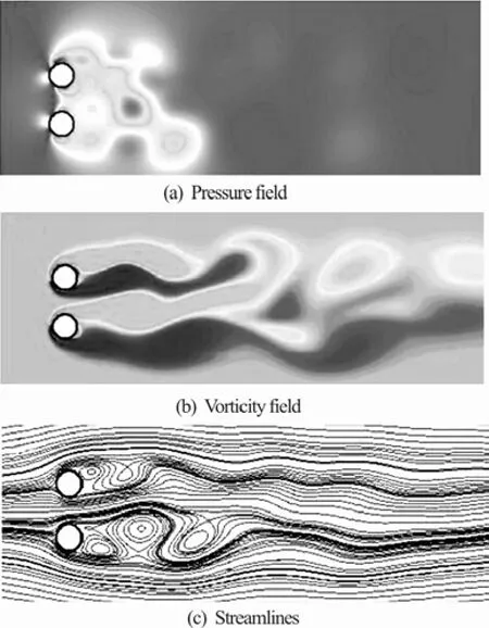
Fig.16 Flow characteristics for two side-by-side cylinders at Re =104, T/D=2 and tU/D =65
The time histories of lift and drag forces at Re =200 and T/ D=2 , 4 are depicted in Figs.14 and 15. At T/ D =1.5, the hydrodynamic forces vary irregularly with time like the similar case at Re=100. No repeatability is predicted in the variations of these coef ficients and therefore th ey f ollow a certain pattern. Theoscillationamplitudesandmeanvaluesofdragcoefficients are the same for both cylinders and the pattern of these oscillations corroborate the flip-flopping phenomenon. As the flow is deflected toward either of two cylinders, drag forces increases. Irregular variation of lift forces reveals the proximity effect between cylinders due to the small spacing.
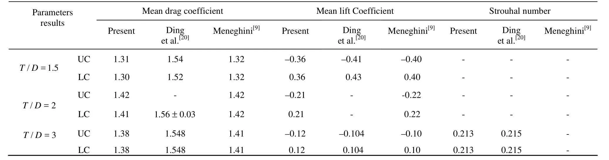
Table 3 Comparison of flow parameters for two side-by-side cylinders at Re=200
At T/ D=2, temporal variations of lift and drag forces are still irregular, where drag force variation represents the flip-flopping pattern and lift force variation demonstrates the net effect of the repulsive force between cylinders, as shown in Fig.14. Amplitude and intensity of lift coefficient and the mean value of drag coefficient increase with respect to the previous case, but the mean value of lift coefficient decreases as the gap increases. It can also be seen that for this gap, T/ D =1.5, a positive mean lift value is experienced by upper cylinder while the lower one takes negative values of lift coefficient. The reason is that while the pressure inside the gap flow is still higher than the pressures at the opposite sides of each cylinder, the pressure drops in the gap flow from the high-pressure region in front of the cylinders to the low-pressure region.
However, by increasing the gap to T/ D =3 the oscillation pattern of hydrodynamic forces shows a significant change with respect to the similar case at Re =100. As is shown in Fig.15, due to the occurrence of two anti-phase wake patterns behind both cylinders (see Fig.13), the synchronization of lift forces from upper and lower cylinders is observed which confirms the synchronized behavior of vortex shedding for this spacing. On the other hand, the antiphase drag forces are the same for both cylinders and their mean values increase again.
Finally, at T/ D =4, the flow shows similar behavior to the one at T/ D =3 except that the mean value of lift coefficient in both cylinders decreases while the mean drag coefficient takes higher values. The lift forces of cylinders are in anti-phase and their mean values are lower than the ones obtained for previous gaps.
A comparison of different flow parameters at Re =200 and different gaps with other numerical and experimental results is presented in Table 3. Generally, it is worth noting that at a given gap, the Strouhal number increases with the increase of the Reynolds number. Due to the existence of unsynchronized wakes for small gaps, i.e., T/ D=1.5, 2, which results from the flopping regime at this gaps, the FFT analysis on lift oscillations shows a spectrum with a broad band without a specific sharp peak. Hence, the Strouhal numbers are not provided for these gaps. 5.3 Turbulent flow, Re=104
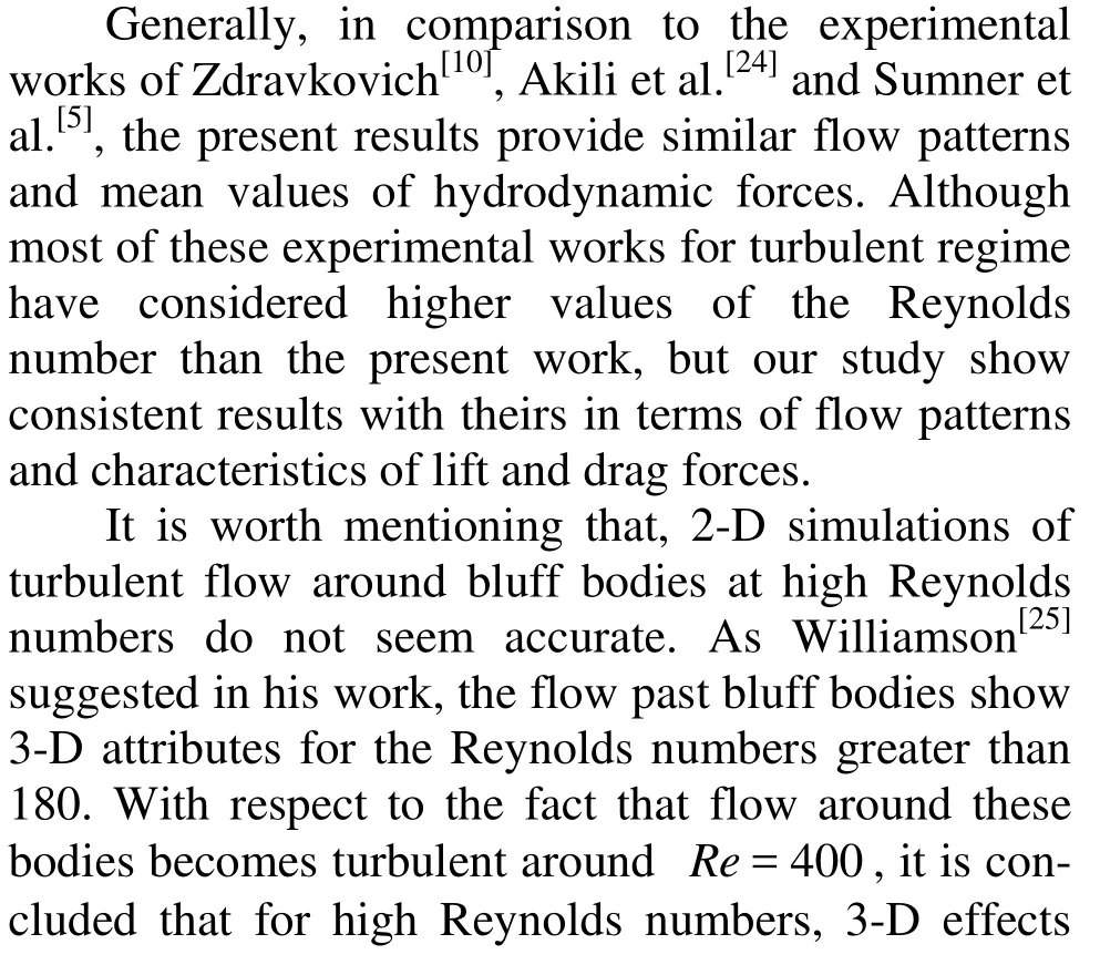
The flow behavior along with characteristics of flow around side-by-side cylinders in laminar flow were discussed and analyzed in the previous sections. Now, we will study the effect of increasing the Reynolds number to subcritical values on the flow over two cylinders in transverse arrangement. As was mentioned in Section 2, each turbulence model satisfies specific conditions. Comparison of obtained results for a single circular cylinder with different k?ε turbulence models reveals that among the three mentioned models, the RNG k?ε model is more appreciable for the present condition of side-by-side cylinders in which separation of flow and shedding of vortices occurs.should be considered in the calculations and hence the grid should be significantly fined which leads to costly calculations. Accordingly, implementation of 2-D methods has attracted much attention. It was observed that using this model with the present code gives reasonable results for mean values and fluctuation amplitudes of the forces.
The simulations were conducted at Re =104for three different gap ratios of T/ D=2, 3 and 4 by using the RNG k?ε model. The non-dimensional time step is set to 0.006. Present simulations for turbulent flow have not been previously presented and analyzed by other researchers.
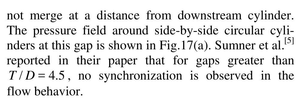
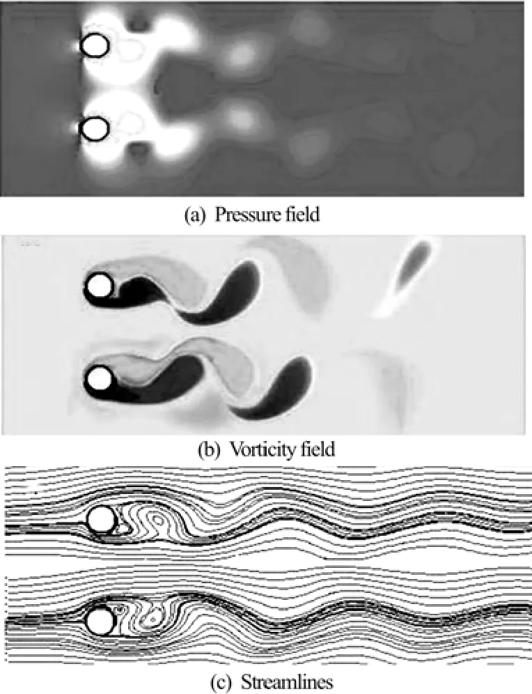
Fig.17 Flow characteristics for two side-by-side cylinders at Re =104, T/D=4 and tU/D=65
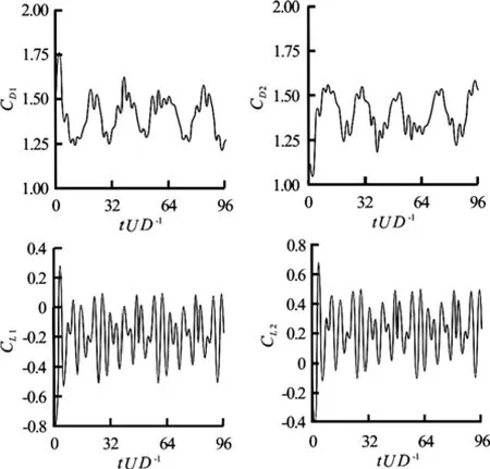
Fig.18 Time histories of lift and drag forces for Re =104and T/D=2
The time histories of lift and drag forces for T/ D =2, 4 and Re =104are shown in Figs.18 and 19, respectively. From these figures, we can observe that increasing the Reynolds number has a significanteffect on the attributes of these forces. Accordingly, from the time histories of lift and drag coefficients in Fig.18 we can perceive that a vivid discrepancy exists for mean drag and lift of both cylinders at T/ D =2 and these mean values are nearly the same for both cylinders. Two reasons can be provided: Firstly, a weaker biased flow exists at this gap ratio, and secondly, during short irregular time intervals this biased flow switches into the opposite direction. The irregular variation of drag coefficients corroborates the flip-flopping phenomenon at this spacing.
Furthermore, due to the symmetric flow pattern at T/ D=3, the upper and lower cylinders show similar trends and symmetric behaviors in terms of drag and lift variations. Corresponding to the antiphase vortex shedding at this gap ratio, the hydrodynamic forces of side-by-side cylinders follow an anti-phase trend at our Reynolds number ( Re =104) while at higher Reynolds numbers there is a probability of in-phase behavior between cylinders. There is a difference in the oscillation amplitudes of lifts and drags for the upper and lower cylinders due to the interference effect but their mean value decays toward same small values.
Fig.19 Time histories of lift and drag forces for Re =104and T/D=4
Finally, From Fig.19 we can clearly observe that as the gap increases to T/ D =4 the interaction between cylinders decreases noticeably, causing the lift forces approach to zero mean values for higher gap ratios. At this spacing, proximity effect diminishes due to the larger spacing between cylinders, both cylinders tend to behave as a single bluff body where their mean value of force coefficients confirms this tendency. As is shown in Fig.19, we can see that unlike previous spacing ratios, at T/ D =4 lift and drag coefficients vary regularly with time as the wake interaction between upper and lower cylinders decreases significantly. The values of different flow parameters for turbulent regime are presented in Table 4. As one can clearly see, by increasing the gap both mean drag and lift values decrease while the Strouhal number increases.
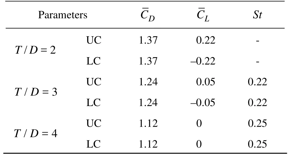
Table 4 Different flow parameters for two side-by-side cylinders at Re =104in present work
6. Concluding remarks
In this paper, a control-volume based solver has been implemented to simulate the flow over two transverse cylinders in laminar and turbulent flows. Different Reynolds numbers and gap ratios have been used in order to investigate the effect of various parameters on flow characteristics and hydrodynamic forces acting on the bodies. Resultantly, the most important conclusions of the present computational simulation of flow over side-by-side cylinders in laminar flow can be summarized as follows:
(1) At Re=100, a biased flow pattern is observed behind both cylinders at T/ D =1.5, which is bistable. Narrow and wide wake regions develop behind each of the cylinders, which change over by time. Also, in-phase vortex shedding is observed for this gap and flip-flopping phenomenon is clearly reproduced. Both lift and drag coefficients of cylinders variy irregularly with time due to the proximity effect. The gap flow is deflected toward the cylinder with higher frequency, which causes this cylinder to experience higher drag.
(2) For higher spacing ratios, T/ D=3, 4, at Re =100 the flip-flopping pattern diminishes as the gap increases. A synchronized anti-phase vortex shedding behind upper and lower cylinders is predicted for T/ D =4, while at T/ D =3 the shedding process and streamlines show an in-phase asymmetric pattern. Since lower cylinder has a higher drag, flow is deflected from this cylinder toward the upper one. The oscillation amplitudes of these cylinders show a slight difference for both T/ D=3, 4, where this difference is smaller f or the latter due t o the d im inishm ent of interferenceeffect.Themeanvaluesoftheseforcesare the same at these gap ratios.
(3) At Re =200, the flow shows similar behavior to that at Re =100 for T/ D =1.5. A repulsive force is developed between cylinders and the wake pattern behind cylinders is similar to that behind a single bluff body. Also, for this gap ratio due to the pressure difference between gap flow and opposite sides of each cylinder, the upper and lower cylinder experience positive and negative lifts, respectively.
(4) At Re =200 and T/ D =2, although the repulsive force between cylinders vanishes but the wake holds the similar pattern of a single cylinder. The wake follows an irregular pattern and flip-flopping phenomenon is observed. Increasing the gap to T/ D =3 causes the flip-flopping phenomenon to diminish and a synchronized anti-phase wake pattern is observed. At T/ D =2, the force coefficients show irregular variation with time like the previous case and the mean value of lift decreases while that of drag increases. As the gap increased to T/ D=3, 4, the mean values of lift and drag decrease and both coefficients follow a certain pattern, implying the synchronized anti-phase pattern at these gaps.
(5) At Re =200, a fully periodic vortex shedding is observed for T/ D =4 and symmetric flow patterns are seen for the higher gaps.
In turbulent regime ( Re =104), the significant conclusions of the present simulation are:
(1) For T/ D =2, a biased asymmetric flow pattern is predicted and wide and narrow wake regions behind upper and lower cylinders intermittently change over with time. At T/ D =3, less wake interaction between cylinders is observed and a synchronized anti-phase vortex shedding is seen for this gap. At T/ D =4 this interactions decreases and a more symmetric flow structure is observed in the streamlines.
(2) The mean values of drag and lift coefficients are discrepant and follow an irregular pattern for T/ D =2 while at higher gap ratios (T/ D=3, 4) they follow a certain pattern and their variations confirm the anti-phase vortex shedding where due to the diminishment of proximity effect at T/ D =4, the behavior of force coefficients are more symmetric at this gap ratio.
Finally, it is worthy to mention that the implemented solver is sufficiently applicable for simulation of flow over complex geometries such as multiple circular cylinders. Also, the presented results can be a good basis for prediction of structural responses in the flexible two side-by-side circular cylinders case.
Also, one can see that mean drag values for the current approach is lower compared to other methods. It should be noted that current approach uses a finite volume method to solve the flow field and hence, leading to more accurate results which may be closer to real values.
[1] ZDRAVKOVICH M. M. The effects of interference between circular cylinders in cross flow[J]. Journal of Fluids and Structures, 1987, 1(2): 239-261.
[2] DENG Jian, REN An-lu and CHEN Wen-qu. Numerical simulation of flow-induced vibration on two circular cylinders in tandem arrangement[J]. Journal of Hydrodynamics, Ser. B, 2005, 17(6): 660-666.
[3] WILLIAMSON C. H. K. Evolution of a single wake behind a pair of bluff bodies[J]. Journal of Fluid Mechanics, 1985, 159: 1-18.
[4] WANG Z. J., ZHOU Y. Vortex interactions in a two side-by-side cylinder near-wake[J]. International Journal of Heat and Fluid Flow, 2005, 26(3): 362-377.
[5] SUMNER D., PRICE S. J. and WONG S. S. T. et al. Flow behavior of side-by-side circular cylinders in steady cross-flow[J]. Journal of Fluids and Structures, 1999, 13(3): 309-338.
[6] ZDRAVKOVICH M. M., PRIDDEN D. L. Interference between two circular cylinders, series of unexpected discontinuities[J]. Journal of Wind Engineering and Industrial Aerodynamics, 1977, 2(3): 305-319.
[7] GUO Xiao-hui, LIN Jian-zhong and TU Cheng-xu et al. Flow past two rotating circular cylinders in a sideby-side arrangement[J]. Journal of Hydrodynamics, 2009, 21(2): 143-151.
[8] SLAOUTI A., STANSBY P. K. Flow around two circular cylinders by the random-vortex method[J]. Journal of Fluids and Structures, 1992, 6(6): 641-670.
[9] MENEGHINI J. R., SALTARA F. and SIQUEIRA C. L. R. et al. Numerical simulation of flow interference between two circular cylinders in tandem and side-byside arrangements[J]. Journal of Fluids and Structures, 2001, 15(2): 327-350.
[10] LIU Kun, MA Dong-jun and SUN De-jun et al. Wake patterns of flow past a pair of circular cylinders in side-by-side arrangements at low Reynolds numbers[J]. Journal of Hydrodynamics, Ser. B, 2007, 19(6): 690-697.
[11] CHEN L., TU J. Y. and YEOH G. H. Numerical simulation of turbulent wake flows behind two side-by-side cylinders[J]. Journal of Fluids and Structures, 2003, 18(3-4): 387-403.
[12] GHADIRI DEHKORDI Behzad, HOURI JAFARI Hamed. Numerical simulation of flow through tube bundles in in-line square and general staggered arrangements[J]. International Journal of Numerical Methods for Heat and Fluid Flow, 2009, 19(8): 1038-1062.
[13] GHADIRI-DEHKORDI Behzad, SARVGHADMOGHADDAM Hesam and HOURI JAFARI Hamed. Numerical simulation of flow over two circular cylinders in tandem arrangement[J]. Journal of Hydrodynamics, 2011, 23(1): 114-126.
[14] PATANKAR S. V. Numerical heat transfer and fluid flow[M]. New York: Hemisphere Publishing, 1980, 4: 133-145.
[15] KANG S. Characteristics of flow over two circular cylinders in a side-by-side arrangement at low Reynoldsnumbers[J]. Physics of Fluids, 2003, 15(9): 2486-2498.
[16] SA J. Y., CHANG K. S. Shedding patterns of the nearwake vortices behind a circular cylinder[J]. International Journal for Numerical Methods in Fluids, 1991, 12(5): 463-474.
[17] LEE K., YANG K. S. Flow patterns past two circular cylinders in proximity[J]. Computers and Fluids, 2009, 38(4): 778-788.
[18] PARK J., KWON K. and CHOI H. Numerical simulations of flow past a circular cylinder at Reynolds numbers up to 160[J]. Journal of Mechanical Science and Technology, 1998, 12(6): 1200-1205.
[19] BEARMANN P. W., WADCOCK A. J. The interaction between a pair of circular cylinders normal to a stream[J]. Journal of Fluid Mechanics, 1973, 61: 499-511.
[20] DING H., SHU C. and YEO K. S. et al. Numerical simulation of flows around two circular cylinders by mesh-free least square-based finite difference methods[J]. International Journal for Numerical Methods in Fluids, 2007, 53(2): 305-332.
[21] LIANG C., PREMASUTHAN S. and JAMESON A. High-order accurate simulation of low-mach laminar flow past two side-by-side cylinders using spectral difference method[J]. Computers and Structures, 2009, 87(11-12): 812-827.
[22] ZHOU Y., WANG Z. J. and SO R. M. C. et al. Free vibrations of two side-by-side cylinders in a crossflow[J]. Journal of Fluid Mechanics, 2001, 443: 197-229.
[23] XU S. J., ZHOU Y. and SO R. M. C. Reynolds number effects on the flow structure behind two side-by-side cylinders[J]. Physics of Fluids, 2003, 15(5): 1214-1219.
[24] AKILI H., AKAR A. and KARAKUS C. Flow characteristics of circular cylinders arranged side-by-side in shallow water[J]. Flow measurement and Instrumentation, 2004, 15(4): 187-197.
[25] WILLIAMSON C. H. K. 2-D and 3-D aspects of the wake of a cylinder, and their relation to wake computations[J]. Vortex Dynamics and Vortex Methods, 1991, 28: 719-751.
10.1016/S1001-6058(10)60178-3
* Biography: SARVGHAD-MOGHADDAM Hesam (1984-), Male, Master

- 水動力學研究與進展 B輯的其它文章
- LATTICE BOLTZMANN METHOD SIMULATIONS FOR MULTIPHASE FLUIDS WITH REDICH-KWONG EQUATION OF STATE*
- NUMERICAL SIMULATION OF HYDRODYNAMIC CHARACTERISTICS ON AN ARC CROWN WALL USING VOLUME OF FLUID METHOD BASED ON BFC*
- DYNAMIC ANALYSIS OF FLUID–STRUCTURE INTERACTION OF ENDOLYMPH AND CUPULA IN THE LATERAL SEMICIRCULAR CANAL OF INNER EAR*
- SIMULATIONS OF FLOW INDUCED CORROSION IN API DRILLPIPE CONNECTOR*
- NUMERICAL STUDY OF HYDRODYNAMICS OF MULTIPLE TANDEM JETS IN CROSS FLOW*
- EXPERIMENTAL STUDY ON SEDIMENT RESUSPENSION IN TAIHU LAKE UNDER DIFFERENT HYDRODYNAMIC DISTURBANCES*