
Dark NoC: Hurdling the Power and Temperature Budgets from Communication Perspective
2014-03-24 05:40TengFeiWangWenMingPanandBaoXinZhao
Teng-Fei Wang, Wen-Ming Pan, and Bao-Xin Zhao
Dark NoC: Hurdling the Power and Temperature Budgets from Communication Perspective
Teng-Fei Wang, Wen-Ming Pan, and Bao-Xin Zhao
——Among the components on a many-core chip, network-on-chip (NoC) has already contributed a large portion to overall power consumption. Optimizing NoC performance under a given power budget is further complicated to keep the network connectivity and minimize the detour distances. In this paper, a NoC power budgeting method from the communication perspective is proposed, which intelligently powers off routers/links and sets up alternative paths to restrict the power and thermal envelop. The effect of performance optimizaion of the proposed power budgeting mothod is measured based on latency and in the given power budget, 22% latency can be reduced averagely compared with some competing methods when running real benchmarks.
Index Terms——Alternative path, configurable switches, dark network-on-chip, hotspot migration.
1. Introduction
With the complementary metal-oxide-semiconductor transistor (CMOS) scaling advancing, the power of chips escalates, which will soon exceed the affordable power budgets. An increasing portion of chips has to be powered off due to the power and thermal envelop, and this phenomenon is called dark silicon[1]. Thus, a paradigm shift occurs, which migrates from traditional low power techniques[2],[3]to power budgeting that optimizes the performance under a given budget[4]-[6].
Most previous work focuses on power budgeting from the computation perspective[4]-[7]. However, the on-chip communication consumes an increasing portion of power. Different from power budgeting from the processor side,power budgeting from the communication side is complicated by the following two requirements: Firstly, the network should remain connected even in case of some parts being powered off; secondly, the detour distance of the traffic affected by some nodes powered off should be minimized to reduce traffic overhead. Fig. 1 shows the schematic of a 16 tiles (router) communication system. Several tiles are powered off in different ways, where network connectivity is broken in (a), the detour distance is quite long in (b), and the suitable scheme is shown in (c).

Fig. 1. Several different ways to power off routers: (a) network connectivity is broken, (b) data detour distance is quite long, and (c) the suitable scheme.
To tackle the aforementioned problems, a method named as dark NoC is proposed in this paper for optimizing the performance of NoC over a given power budget. In the proposed method, we power off part of the network to restrict the power budget, and set up alternative paths to detour the affected flows. Traffic/thermal hotspots are migrated to other regions in the network such that both the temperature and leakage are reduced.
In this paper, our contributions include:
1) We address the power budgeting problem from the communication perspective instead of the popular computation centered approaches.
2) A method to optimize performance under a given power/thermal budget is proposed.
3) New communication channels are set to keep the NoC connectivity and limit the detour distance in the migration of traffic mounts.
4) Our experiments shows that 50% delay in breadth first searching and 22% delay in real benchmarks are reduced compared with several competing methods.
The remainder of this paper is organized as follows. The related works are surveyed in Section 2. Section 3 presents the proposed work in two phases. Experiment results are analyzed and evaluated in Section 4. Section 5 concludes the paper. At the end of this paper, the power and thermal model is demonstrated in Appendix.
2. Related Works
The power efficiency of a many-core system can be improved by either reducing the power consumption for given tasks or maximizing the performance over a given power budget. Lower power techniques, such as [2] and [3], fall into the first category and power budgeting methods, such as [4]-[6], fall into the second category.
Low power techniques involve micro architecture or circuit level innovations to reduce power consumption. A trend is to integrate light weight cores into a chip[4],[8].
On the other hand, many runtime power budgeting methods are proposed to improve the performance and control the power consumption of components to be confined to the power envelop[9],[10], most of which use the dynamic voltage/frequency scaling (DVFS) or power gating (PG) technique to achieve the performance optimizing goal.
However, all the aforementioned methods are computing (processor) centered. In communication perspective, the techniques such as DVFS and PG can also be used, and current methods mainly fall into the low power category. A method named as catnap[11]divides NoC into different subnets based on the virtual channel, and routers and links in different subnets are dynamically powered off. The segment gating method discussed in [12] also gates components in NoC but in a different way compared with the catnap. The method based on communication throttle[13]provides another view, which does not reduce power consumption but blocks the communication traffics outside the network when power is insufficient.
Our work proposed here also takes the power gating technique into usage. However, compared with the catnap and segment gating methods, the power budgeting idea is achieved to restrict a power budget with limited performance degrading. Compared with the throttle method, the object to be restricted is power consumption but not communication traffics. Our work also involves alternative path setup, which relies on express channels[14]-[16]. The similar ways of setting up express channels can be found in [17].
3. Dark NoC Approach
3.1 Motivation and Overview
The power consumed by NoC is distributed in every router and link, and among which the power consumed by routers is dominant in the total power budget. A directly thought is to gate some nodes of NoC to restrict consumption when the power budget is insufficient. However, an appropriate gating scheme should be chosen, otherwise the network connectivity problem and detour distance problem shown in Fig. 1 will be met. In addition, when the portion of dark nodes is continually increasing, the latency of communication will increase continually for correct transmission, as massive communication flows have to be blocked in the surviving active nodes. So a linear decrease in active NoC components may not result in a linear decrease in performance, but even worse.
In practical, for most applications performed in a many-core system, the workloads of different processors vary greatly, so is the workloads of the related nodes in NoC. On the other hand, the nodes with less traffic volume also consume a fair amount of leakage power, which contributes a significant portion to the overall budget[18]in the newest techniques. The proposed power budgeting method aims to optimize the NoC performance in different power budget levels, so low traffic volume nodes are selected to be dark to minimize the effect to the total performance and also to minimize the leakage power consumption.
The framework of the proposed dark NoC approach consists of two main phases. A master core performs the path setup and the communication flows of every node are recorded at runtime for predicting of future traffic patterns. The setup of the dark NoC will be updated once in every time period. The basic steps of the dark NoC approach include:
Phase 1: Dark nodes planning. Select routers with low traffic volume to power off so as to limit the power budget.
Phase 2: Alternative paths setup. Set up point-to-point paths by configurable switches to redirect the traffic flows affected by the dark nodes.
By the way, the thermal/traffic hotspot is considered to be migrated and distributed to alter nodes to reduce both the temperature and leakage power by configurable switches. And the switch connecting method is the same as that in Phase 2.
Main challenges in these phases fall in:
i) When selecting nodes to be off, not only the power budget, but also the effect to communication efficiency should be taken into consideration.
ii) Point-to-point alternative data paths should be set for every affected communication flow, and they should be able to keep the network connectivity and restrict the detour distance under the condition that they will not overlap with each other to prevent the communication conflicts and data blocking.
The proposed dark nodes selection and alternative paths setup method are introduced in detail in the following sections and we discuss the proposed method based on a 2-dimension (2D) mesh NoC.
3.2 Dark Node Planning
We select nodes with low traffic volume to be off to weaken the effect to the normal communication. There are three steps in dark node planning, which are monitoring the activity of each router, selecting routers with low utilization, and adjusting the selected routers to guarantee network connectivity and limit the detour distance.
The activity of each router can be measured as the number of flits passed through it in a given time. Counters can be equipped at each input buffer to record the number of flits. The master node gets the records periodically and uses the average value in the last three periods to predict the future utilization of each router.
Given the list of utilization of each router, a set of dark routers (DR) with low utilization can be selected out to be powered off. Assume that each router have an average power consumption ofPr(which can be calculated approximately with (7) in Appendix), and the power budget for NoC to use isPin, then the number of DR to be off is

whereNis the total number of routers in NoC.
3.3 Alternative Path Setup
A. Circuit Level Support
When dark nodes are powered off, alternative paths must be set to keep the connectivity of NoC and to redirect the affected communication flows. When setting alternative paths, two hardware circuits are involved: 1) a layer of configurable switches for building paths to bypass the dark nodes, and 2) the backup circuit at each network interface (NI) to inject flows to or eject flows from the network when the corresponding node is off.
The configurable switches can be set in a different way based on different NoC architectures and dimensions. However, in spite of the different complexities and connections between configurable switches, the same principle is in use as the architecture of a 2D mesh network shown in Fig. 2. Every configurable switch is related with one node in NoC, and links in configurable switches layer keep the parallel direction with the links in NoC.
The link between each router and configurable switch is switched with a multiplexer to connect with NI directly as shown in Fig. 3.

Fig. 2. Alternative path will be set with configurable switches layer for communication flows affected by dark nodes.

Fig. 3. Bypass circuits at each NI. The muliplexer will switch to (a) router or (b) NI to inject the traffic depending on the on/off status of the routers. Circuits for traffic ejection are similar.
In the upper two circuits, the configurable switches consist of several gates and multiplexers circuits, and the architecture of each configurable switch can be seen in Fig. 4, where E, W, S, N, and L mean five routing directions in mesh NoC, respectively.

Fig. 4. Circuit architecture of configurable switch.
Two kinds of communication flows in NoC will be affected by dark nodes: A) Those communication flows passing through the dark nodes according to their original routing paths and B) Those communication flows injected into/ejected out from the dark nodes. For type A, the communication flows passing through the dark nodes can be redirected by alternative paths in the configurable switch layer. For type B, the communication flows are performed to inject into/eject out of NI directly with circuits and mechanism shown in Fig. 3.
B. Path Setup
The alternative paths are just created with configurable switches and links, which do not have any flow control and routing capitation capacities. Thus, the key issue in alternative paths setup is to avoid overlap in the configurable switches layer. The problem can be described as that setting up alternative paths for dark nodes affected flows such that the new paths have the minimum overlap and the total distance of all the involved paths is minimized[17].
Suppose the flows affected by dark nodes are sorted in set AF. For a given flow afiin AF, all its minimal paths are enclosed in the set MPi, withrepresenting thetotal number of minimal paths of flow afi. mpi,k∈MPirepresents thekth minimal path of flow afi. A binary variable afi,kis used to indicate whether thekth minimal path of flow afiis set up or not, where afi,k=1 means thekth path is connected for flow afi. Let PATHi,jbe the set of links on thejth minimal path taken by the flow afiin the configurable switches layer. LetVbe the maximum number of flows sharing one link. Each configurable switchphas a set of binary variables, whererepresents the connection from the input portXto the output portY. And the value 1 means these two ports in switchpare connected, whereXandYcorrespond to elements in E, W, S, N, and L.
The paths setup has a constraint from the configurable switch ports, i.e., one input port can only be connected to one output port in this switch. These two connected ports are called a pair of ports. LetQbe the number of pairs of ports that are connected within one configurable switch. The maximum value ofQis 5, as shown in Fig. 5.

Fig. 5. Examples for the maximal number of connections in one configurable switch.
Then, the problem of setting alternative paths can be formulated as: min(V+Q), subject to


Equation (2) ensures exactly one path is established for each affected flow. Equation (3) tries to minimize the overlap among the links in the configurable switches layer. Equation (4) minimizes the overlap inside each configurable switch, e.g., an input should not be connected to more than one output. Equation (5) ensures that if a flow’s path makes a turn from directionXtoYinside a configurable switchp,will be set as 1 when this path is setup.
In real solution, a searching based method is used. Initial alternative paths in the configurable switches layer are set along the direction the same as the dimension routing to avoid deadlock, and we build a path queue to record the flow ID and the relating alternative path in pair that have been set up. New alternative paths which select the unused links will be added to the queue. And these flows which cannot find alternative paths will be blocked in their source router temporarily until some links are available. At the same time, the old paths will be removed from the queue after the affected flows are posted dynamically. This procedure that builds the path queue can be described by Fig. 6.

Fig. 6. Alternative path queue setup procedure.
C. Practical Concerns of Thermal Budgets
Temperature and power form a position loop, i.e., the greater traffic leads to the higher dynamic power which in turn increases the temperature and finally the leakage is increased exponentially. This becomes a particularly severe problem in nodes as the source of one-to-many communications.
However, if we can distribute the traffic of the one-to-many traffic hotspot, and thus reduce the activity of it, the temperature can be reduced, which eventually leads to an exponentially reduction in the leakage, as shown in Fig. 7. The traffic of the memory controllerT1is migrated to the nodes labeled asT2, by the same bypass links in the configurable switches layer. In this situation, although the temperature of nodes labeled asT2will increase, in total the reduction in the leakage will be greater than that caused by the slight temperature increase in the fourT2nodes, as the relationship between the leakage and temperature obeys an exponential law.

Fig. 7. Example to migrate thermal hotspot.
For a one-to-many traffic hotspot, nodes (named as agent nodes) are selected to distribute the traffic by the bypass links, which are set in the same way with the alternative paths of flows affected by the dark nodes. The network is partitioned intoMclusters virtually, and the center of each cluster is selected as an agent node.
4. Experiment Results
4.1 Experiment Setup
Simulation experiments are performed with an in-house developed simulator, where Orion[19]is integrated to calculate the power consumption of NoC, McPAT[20]operates the processor simulation, CACTI[21]models the cache and memory, and Hotspot[22]simulates the variation of temperature. The simulation configurations are set similarly to the Intel 80-tiles Teraflops chip[23]and detailed simulator setting can be seen in Table 1.

Table 1: Setup of experiment simulator
The evaluation is performed over a suite of benchmarks: BFS with 4 synthetic graphs from TGFF as the input data, 7 benchmarks in PARSEC[24], and 2 benchmarks in SPLASH-2[25], which are listed in Table 2. In the following, we will compare the proposed method against the catnap[11]method, where NoC is partitioned into subnets and different subnets can be dynamically powered off according the virtual channels in use, and the throttle[13]method, where traffics are prevented from entering the network if power budget is insufficient.

Table 2: Benchmarks
4.2 Performance Analysis
A. Execution Time
In these experiments, the execution time is recorded as the quantitative index to validate the performance of the proposed method, the catnap, and throttle methods for comparison. The execution time of BFS with different NoC traffic (different sizes of graphs for BFS input) under a 50 W power budget is shown in Fig. 8. The execution time of the proposed method is reduced by 50.2% and 53.1% compared with that of the catnap and throttle methods averagely. When the given power budgets changes from 60 W to 40 W, the similar conclusion can be derived out as shown in Fig. 9. It shows a bursting of performance in these experiments with the proposed method.
The execution time of PARSEC sets and SPLASH-2 sets in the budget of 50 W can be seen in Fig. 10. Compared with the catnap and throttle methods, the execution time can be reduced averagely by 15.9% and 19.9%, respectively. While, compared with the BFS experiments, the performance is not promoted so distinctly, because there are evidently a few one-to-many traffic hotspots in the application setup and the execution time is mainly increased by the alternative links of the dark nodes.

Fig. 8. Execution times of BFS with different size (500, 1000, 2000, 3000) graphs as input under 50 W power budget.

Fig. 9. Execution times of BFS with 3000 vertex graphs as input set, while power budget changes from 60 W to 40 W.

Fig. 10. Normalized execution times for nine real benchmark sets with 50 W input budget.

Fig. 11. Normalized execution times of real benchmark sets in a 6×6 mesh with 50 W input budget.
B. Scalability
The proposed method can be generalized for different sizes of networks. The execution time of APRSEC and SPLASH-2 sets with a 6×6 mesh network is shown in Fig. 11 and it demonstrates the scalability of the proposed method is fine, for the execution time is reduced averagely by 20.4% and 23.5% for the two sets, respectively. The results show that the proposed method is enough flexible and scalable to be used in different network situations.
C. Leakage Reduction
The leakage reduction effect is simulated independently by using the BFS experiments with the different sizes of synthetic graphs as the input. The maximal temperature of the on-chip network components and normalized leakage power consumption can be seen in Fig. 12 and Fig. 13, respectively. The results show that the maximal temperature decrease is 50 K and the leakage reduction is 6% to 20% corresponding to different BFS traffics.

Fig. 12. Maximal temperature in BFS (with different sizes of graphs as input).
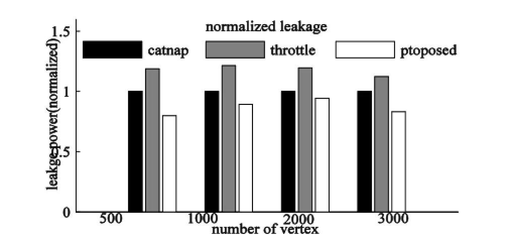
Fig. 13. Normalized leakage power in BFS (with different sizes of graphs as input).
From the above experiments, the proposed method costs less execution time, that is, higher performance for the same power budget and less leakage power consumption compared with the two competitive methods. At the same time with reducing the leakage, the proposed method can keep the communication bandwidth compared with the catnap method and the communication flows will be accelerated by bypass links but not to be blocked outside the network compared with the throttle method.
4.3 Cost of Dark NoC Method
The costs of the proposed method include two parts: the runtime of the alternative paths setup and hardware cost. For the first part, the most time is consumed in the setup of dark nodes and the search of the non-overlapped alternative paths. The time cost of dark nodes setup can be quite little. The procedure of getting the utilization rate of every nodes, sorting the nodes traffic list, and setting up the dark nodes can be restricted in 105 cycles for an 8×8 mesh. This time cost just occurs when dark nodes are updated (we set update period as 5 M cycles). Alternative paths searching time is a variable depending on the number of dark nodes and the affected flows. However, the detection of affected flows and the setup of alternative paths are dynamically performed and can be operated in parallel to the communication.
The hardware cost includes the cost of the configurable switches layer, bypass multiplexers in each NI, and the memory for storing of dark node parameters. Assume that all links are sorted in the alternative paths tree, and the memory requirement for the master core to store these paths is about 10 KB. Setting the working frequency is set as 1 GHz and the size of each node in the flit-switching NoC is 1×1 mm2. The length of a link in the configurable switches layer is 2 mm, because four tiles are connected to be a “meta-node” in the mesh NoC. Each of the configurable switches has an area of 1075 μm2and consumes 6.25 μW dynamic power, and each multiplexer costs an area of 14.88 μm2and consumes 2.514 μW dynamic power (the switching activity is 0.5) in the design by using the Synopsys design compiler under the 45 nm TSMC library. The area and dynamic power of a link are about 0.866 μm2and 0.09 μW (the switching activity is 0.5), with the 45 nm technology available from the ORION 2.0 simulator.
5. Conclusions
As the many-core design enters the dark silicon era, a design paradigm occurs, which shifts from the conditional low power design to power budgeting to optimize the performance over a power budget. As NoC is becoming an important power consumer, this work tries to address the problem from the general perspective to optimizing theNoC performance over a given power budget. However, this problem is complicated by two requirements: The network should be connected and the detour distance should be minimized. Thus, we propose an approach to dynamically power off routers/links to restrict the power budget, and setting up alternative paths for the affected traffic flows by configurable switches. And a thermal budget aware traffic migration is used for the hotspot, which is the alternative path for multiple flows affected by the dark nodes, to reduce both of the temperature and leakage. Experiments results shows that the execution time reduces by 50% in BFS and 22% in real benchmarks averagely, and the leakage reduces by 6% to 20% compared with two competing methods. The overhead of the approach is small, which makes it suitable to optimize the NoC performance under a power/thermal budget.
Appendix
A) Power Model
The power (energy) consumed in NoC can be modeled as two parts, dynamic power and leakage power:

The dynamic power is composed of both power consumed in computation and in communication by routers and links. For any componenti, the dynamic power can be calculated as

whereθis the switching activity,Ciis the load capacitance,fis the frequency, andVddis the supply voltage.
The leakage power is caused by the sub-threshold currentIsub0and the gate leakage currentIg0of CMOS, and it will change exponentially depending on the temperature. For any componenti, its leakage power in any transient timeτcan be formulated as

whereTi(τ) is the temperature of the componentiin timeτ,Trefis the reference temperature,Ris the leakage power at the reference temperature, andβis the scaling factor between CMOS technology nodes.
B) Thermal Model
As indicated in [22], the heat flow can be modeled as:

whereτis the discrete time unit, C is the thermal capacitance matrix of components (routers, processors, etc.), A is the thermal conductance matrix, T (τ) is the temperature vector withTi(τ) representing the temperature of theith component, and P(τ) is the power vector including both dynamic and leakage power. Whenτapproaches the infinity, the thermal model can be expressed as

[1] H. Esmaeilzadeh, E. Blem, R. S. Amant, K. Sankaralingam, and D. Burger, “Dark silicon and the end of multicore scaling,” inProc. of Int. Symposium on Computer Architecture, San Jose, 2011, pp. 365-376.
[2] K. Ma, X. Wang, and Y. Wang, “DPPC: dynamic power partitioning and control for improved chip multiprocessor performance,”IEEE Trans. on Computers, vol. 63, no. 7, pp. 1736-1750, 2014.
[3] L. Shang, L. S. Peh, and N. K. Jha, “Dynamic voltage scaling with links for power optimization of interconnection networks,” inProc. of Int. Symposium on High-Performance Computer Architecture, Anaheim, 2003, pp. 91-102.
[4] S. Borkar, “Thousand core chips: a technology perspective,”inProc. of Design Automation Conf., San Jose, 2007, pp. 746-749.
[5] J. S. Kim, M. B. Taylor, J. Miller, and D. Wentzlaff, “Energy characterization of a tiled architecture processor with on-chip networks,” inProc. of Int. Symposium on Low Power Electronics and Design, Seoul, 2003, pp. 424-427.
[6] Y. Hoskote, S. Vangal, A. Singh, N. Borkar, and S. Borkar,“A 5 GHz mesh interconnect for a teraflops processor,”IEEE Micro Magazine, vol. 27, no. 5, pp. 51-61, 2007.
[7] K. Latif, A. Rahmani, T. Seceleanu, and H. Tenhunen,“Power-and performance-aware IP mapping for NoC-based MPSoC platforms,” inProc. IEEE Int. Conf. on Electronics, Athens, 2010, pp. 758-761.
[8] C. Batten, A. Joshi, J. Orcutt, A. Khilo, B. Moss, C. W. Holzwarth, and J. L. Hoyt, “Building many-core processor-to-DRAM networks with monolithic CMOS silicon photonics,”IEEE Micro Magazine, vol. 29, no. 4, pp. 8-21, 2009.
[9] M. Berezecki, E. Frachtenberg, M. Paleczny, and K. Steele,“Many-core key-value store,” inProc. of Int. Green Computing Conf. and Workshops, Orlando, 2011, pp. 1-8.
[10] S. Gálvez, D. Díaz, P. Hernández, F. J. Esteban, J. A. Caballero, and G. Dorado, “Next-generation bioinformatics: using many-core processor architecture to develop a web service for sequence alignment,”Bioinformatics,vol. 26, no. 5, pp. 683-686, 2010.
[11] R. Das, S. Narayanasamy, S. K. Satpathy, and R. G. Dreslinski, “Catnap: energy proportional multiple network-on-chip,” inProc. Int. Symposium on Computer Architecture, Tel-Aviv, 2013, pp. 320-331.
[12] K. C. Hale, B. Grot, and S. W. Keckler, “Segment gating for static energy reduction in networks-on-chip,” inProc. of Int. Workshop on Network on Chip Architectures, New York, 2009, pp. 57-62.
[13] Y. Jin, E. J. Kim, and K. H. Yum, “Peak power control for a QoS capable on-chip network,” inProc. of Int. Conf. on Parallel Processing, Washington, DC, 2005, pp. 585-592.
[14] C. Jackson and S. J. Hollis, “Skip-links: a dynamically reconfiguring topology for energy-efficient nocs,” inProc. of Int. Symposium on System on Chip, Tampere, 2010, pp. 49-54.
[15] A. Kumar, L.-S. Peh, and N. K. Jha, “Express virtual channels: Towards the ideal interconnection fabric,” inProc. of the 34th Annual Int. Symposium on Computer Architecture, San Diego, 2007, pp. 150-161.
[16] S. Hollis, C. Jackson, P. Bogdan, and R. Marculescu,“Exploiting emergence in on-chip interconnects,”IEEE Trans. on Computers,vol. 63, no. 3, pp. 570-582, 2012.
[17] X. Wang, T. Mak, M. Yang, Y. Jiang, M. Daneshtalab, and M. Palesi, “On self-tuning networks-on-chip for dynamic network-flow dominance adaptation,” inProc. of IEEE/ACM Int. Symposium on Networks on Chip, Tempe, 2013, pp. 1-8.
[18] Managing power in 45 nm and 65 nm designs. [Online]. Available: http://www.dianzichan.com/anonymous/ic/arm07 conf_mgm_pwr45nm.pdf
[19] A. B. Kahng, B. Li, L.-S. Peh. and K. Samadi, “Orion 2.0: a power-area simulator for interconnection networks,”IEEE Trans. on Very Large Scale Integration Systems,vol. 20, no. 1, pp. 191-196, 2012.
[20] S. Li, J. H. Ahn , R. D. Strong, J. B. Brockman, D. M. Tullsen, and N. P. Jouppi, “McPAT: an integrated power, area, and timing modeling framework for multicore and manycore architectures,” inProc. of the 42nd IEEE/ACM Int. Symposium on Microarchitecture, New York, 2009, pp. 469-480.
[21] N. Muralimanohar, R. Balasubramonian, and N. P. Jouppi,“CACTI 6.0: a tool to model large caches,”HP Laboratories, 2009.
[22] W. Huang, S. Ghosh, S. Velusamy, K. Sankaranarayanan, K. Skadron, and M. R. Stan, “HotSpot: a compact thermal modeling methodology for early-stage VLSI design,”IEEE Trans. on Very Large Scale Integration Systems,vol. 14, no. 5, pp. 501-513, 2006.
[23] S. R. Vangal, J. Howard, G. Ruhl, S. Dighe, H. Wilson, J. Tschanz, D. Finan, A. Singh, T. Jacob, and S. Jain, “An 80-tile sub-100-w teraflops processor in 65 nm CMOS,”IEEE Journal of Solid-State Circuits,vol. 43, no. 1, pp. 29-41, 2008.
[24] C. Bienia, S. Kumar, J. P. Singh, and K. Li, “The PARSEC benchmark suite: characterization and architectural implications,” inProc. of Int. Conf. on Parallel Architectures and Compilation Techniques, 2008, pp. 72-81.
[25] S. C. Woo, M. Ohara, E. Torrie, J. P. Singh, and A. Gupta,“The SPLASH-2 programs: characterization and methodological considerations,” inProc. of the 22nd Annual Int. Symposium on Couputer Architecture, Santa Margherita Ligure, 1995, pp. 24-36.

Teng-Fei Wang was born in Henan, China in 1989. He received the B.S. and M.S. degrees from the Wuhan University, Wuhan in 2011 and 2013, respectively, both in electrical engineering. He is currently a research assistant with Guangzhou Institute of Advanced Technology, Chinese Academy of Sciences. His research interests include parallel computing, many-core system and communication networks.

Wen-Ming Pan was born in Guangdong, China in 1982. He received the B.S. and M.S. degrees in electronic engineering from Jinan University, Guangzhou in 2004 and 2007, respectively. He works as a research assistant with Guangzhou Institute of Advanced Technology, Chinese Academy of Sciences. He has been engaged in the FPGA design research for years. His research interests include networks-on-chip and parallel computing.

Bao-Xin Zhao was born in Shandong, China in 1987. He received the B.S. degree in electric science and technology from Shandong Agriculture University, Tai’an in 2007, and the M.S. degree in computer science and technology from Guangdong University of Technology, Guangzhou in 2014, respectively. He is currently pursuing the doctoral degree in computer science with University of Chinese Academy of Sciences. His research interests include computer architectures, NoC system simulation, and energy-efficient design.
Manuscript received August 11, 2014; revised November 28, 2014. This work was supported by the National Natural Science Foundation of China under Grant No. 61376024 and No. 61306024, Natural Science Foundation of Guangdong Province under Grant No. S2013040014366, and Basic Research Programme of Shenzhen No. JCYJ20140417113430642 and No. JCYJ20140901003939020.
T.-F. Wang is with Guangzhou Institute of Advanced Technology, Chinese Academy of Sciences, Guangzhou 511458, China (Corresponding author e-mail: tf.wang@giat.ac.cn).
W.-M. Pan and B.-X. Zhao are with Guangzhou Institute of Advanced Technology, Chinese Academy of Sciences, Guangzhou 511458, China (e-mail:wm.pan@giat.ac.cn; bx.zhao@giat.ac.cn).
Digital Object Identifier: 10.3969/j.issn.1674-862X.2014.04.002
 Journal of Electronic Science and Technology2014年4期
- Journal of Electronic Science and Technology的其它文章
- Study on Temperature Distribution of Specimens Tested on the Gleeble 3800 at Hot Forming Conditions
- Automatic Vessel Segmentation on Retinal Images
- Family Competition Pheromone Genetic Algorithm for Comparative Genome Assembly
- Quantification of Cranial Asymmetry in Infants by Facial Feature Extraction
- Intrinsic Limits of Electron Mobility inModulation-Doped AlGaN/GaN 2D Electron Gas by Phonon Scattering
- Real-Time Hand Motion Parameter Estimation with Feature Point Detection Using Kinect