
CFD-based optimization and design of multi-channel inorganic membrane tubes☆
2016-05-26 09:28ZhaoYangJingcaiChengChaoYangBinLiang
Zhao Yang,Jingcai Cheng*,Chao Yang*,Bin Liang
1College of Chemical Engineering,Sichuan University,Chengdu 610065,China
2Key Laboratory of Green Process and Engineering,Institute of Process Engineering,CAS,Beijing 100190,China
1.Introduction
Over the past three decades,membrane separation has received increased attention and played a more and more important role in industrial separation processes,due to its advantages of high efficiency and easy operation[1–3].Porous inorganic membranes(e.g.Al2O3,TiO2and ZrO2)with their various advantages,such as better thermal,chemical and mechanical resistance,controllable micro-structure and little pollution to the environment,have been widely applied in the fields of bioengineering,environment engineering,chemical and petrochemical industry[4–6].Kinds of membranes(ceramic membrane,zeolite membrane,metallic membrane,organo-inorganic composite membrane,etc.)designed for various membrane separation processes such as micro filtration(MF),ultra filtration(UF),nano filtration(NF),and reverse osmosis(RO)have come to the fore[7–10].
Membrane separation,usually a pressure-driven process,in which a feed stream passes a semi-permeable membrane(generally in a cross flow configuration),and mass transfer is facilitated by hydraulic pressure through the membrane to achieve separation into permeate(‘clean’)and concentrate(‘dirty’)streams[11].A number of studies have focused on enhancing membrane filtration by optimizing the con figuration of membrane element and operating conditions for filtration.For example,inorganic membranes are generally manufactured in fl at-disk,tubular or multi-channel monolithic configurations[12].Due to their excellent mechanical strength and large exchange surface,multi-channel membrane elements,which are provided by monolithic porous support body with channels passing through it,are widely applied in industry.As shown in Table 1,almost all the commercialized ceramic membrane products are multi-channel membrane elements.And most of the channels are cylindrical though some other shapes like flabellate channels(Tami Inc.,France)and square channels(Novasep Inc.,France)exist.In order to obtain large exchange surface,some membrane elements comprise more than one hundred channels,such as the ceramic honeycomb membrane developed by CeraMem Corp.The performance of a membrane separation process can be characterized by the product of the total filtration area and the membrane permeate flux,which suggests two main ways to optimize the configuration of multi-channel membrane elements:increasing membrane filtration area and increasing the membrane permeate flux.
Principal strategies for increasing membrane filtration area are modifying the channel shape and increasing the channel number.Changing the shape of channels from cylindrical to square,hexagonal,triangular,fan-shaped,petal shaped etc.could increase the membrane filtration area[13–15],but cylindrical channels are the most widely used because of their easy process ability and their advantages in decreasing the membrane pollution and back- flushing effect.Increasing the number of membrane channels is another way to increase the membrane filtration area,but it also causes the increase of membrane tube diameter.Membrane diameter may vary but it must fall within acceptable manufacturing limits.The manufacture of a large-diameter membrane is complicated (long drying time, lower yield)where as the manufacture of a small-diameter membrane implies higher production cost of a whole unit(labor and handling)[15].Meanwhile,a membrane tube with a large number of channels may have the problem of different permeate fluxes among channels at different locations,which brings constraints to the average membrane permeate flux.The honeycomb membrane elements with a large number of channels well arranged,to some extent,solved the problem above by grooving.But there exist a technical barrier to manufacturing large honeycomb membrane elements of high quality.As a consequence,cylindrical multi-channels(e.g.,7,19,37-channels)membrane tubes have been the most widely adopted ones in industry.

Table 1 Typical configurations of ceramic membranes
Many scholars have studied the membrane filtration processes by CFD simulations,through which a better understanding of the complex membrane filtration processes can be obtained and the number of experiments can be reduced[11].The first simulations of flow in membranes were carried out in channels with porous walls and under laminar conditions by Berman[16]and Terrill[17].Berman's approach was extended by Galowin and De Santis[18]and Karode[19].Recent numerical treatments of laminar flow through a porous membrane have followed a similar approach,by using both the Navier–Stokes equations and the Darcy equation[20–22].By the development of the method,many specific cases could be treated under laminar conditions[11,23].However,some researchers proved it necessary to work under turbulent conditions[24–26].A very interesting simulation by Tarabara et al.[27]showed that the geometry played an important role in the membrane enhancement and that it was highly possible to optimize membrane geometry by using CFD.Dolecek[28]studied the effect of geometry parameters on the performance of a simple rectangular honeycomb configuration numerically using the finite element method,but lacking of experimental data to verify the calculation results.Then Dolecek et al.[29]simulated the permeation flow in a porous support of inorganic 19-channel membrane and concluded that the enhancement of membrane performance was not generally proportional to the increase in filtration channels.And the predictions were not in an excellent agreement with experimental results,which might be caused by modeling the asymmetric internal membrane structure inaccurately or just simulating the permeation flow in a two-dimensional model.
To date,CFD simulations on the membrane separation processes were generally performed using the simplified 2D models.Three dimensional models could provide more detailed and accurate information on the complex flow in membranes,which therefore would be more advantageous to the aided design of membrane elements.However,high computational expense for 3D models means that they can only be feasible for small representative portions of the membrane channel where spatially periodic flow conditions exist,which is generally not the case[11].Applying an effective simplified calculation 3D model,the authors of this article have simulated the permeation flow in an asymmetric ceramic membrane tube in a previous work[30].With consideration of turbulence in channels,the predicted results were in good agreement with the experimental results.
In order to make the research and optimization results of this work become a good technique for decreasing cost and boosting productivity,a cylindrical 37-channel inorganic porous membrane tube was selected as the research and optimization objective.The configuration of the multi-channel membrane tube was optimized by increasing the membrane filtration area and the membrane permeate flux.First,the size relationship between the channel diameter and inter-channel distance was studied using a theoretical analysis method,which is another factor affecting the total membrane filtration area of multi-channel membrane tubes and less reported in the literature.Then,the permeation flow of pure water in the porous ceramic cylindrical 37-channel membrane tube was simulated based on our previous work on the simulation of the permeation flow in a single channel membrane tube[30].The relationship between the permeation efficiency and channel locations,and the method for increasing the permeation efficiency of inner channels were proposed.Some novel multi-channel membrane configurations with more permeate side channels were put forward and evaluated.
2.Materials and Method
2.1.Optimization of membrane tube parameters
Membrane filtration area of multi-channel membrane tubes can be expressed in absolute and relative membrane values.The relative membrane area means the ratio of absolute membrane area to the membrane tube's volume(area–volume ratio),which is related to the permeation efficiency of a membrane tube and is also concerned about.
Several fundamental factors need to be considered when designing a multi-channel inorganic membrane tube. To fulfill the goal of increasing the area–volume ratio,the impacts of channel diameter,inter-channel distance and channel number on the area–volume ratio were investigated.
A cylindrical 37-channel membrane tube with equilateral triangle arrangement is shown in Fig.1,where d is the channel diameter,a is the inter-channel wall-to-wall distance(edge thickness),D is the outer diameter of the membrane tube,Smis the absolute membrane area,Vtis the volume of the membrane tube,β is the area–volume ratio and h is the length of the membrane tube.Then

Fig.1.Cross section diagram of a cylindrical 37-channel membrane tube with equilateral triangle arrangement.

2.2.Simulation of permeate flow
For the multi-channel membrane tube,the permeate flux or the permeation efficiency of inner channels closer to the center of the membrane tube is usually smaller,which lowers the average membrane permeate flux of the membrane tube.In order to improve the permeate flux of a multi-channel membrane tube,the permeate flow of pure water in a 37-channel ceramic membrane was simulated.

Fig.2.The configuration and cross- flow of 37-channel ceramic membrane.
The configuration of a 37-channel ceramic membrane and its cross flow filtration process are shown in Fig.2.Because the channels are arranged axisymmetrically to the axis of the membrane tube,the channels arranged in four rings from the center to the periphery are named as Channel1-1,Channel2-1to2-6,Channel3-1to3-12and Channel4-1 to4-18,respectively.ΓAis the sum of the surface area of all channels,and ΓBis the outermost circumferential surface where the permeating fluid finally flows out.The surface where the permeating fluid finally flows out are called the permeate side in this work.
In order to reduce the resistance,inorganic membranes generally have asymmetric porous structures including a porous support,a membrane skin layer acting as a separating barrier,and maybe some intermediate transition-layers in between.The support body determines the configuration of a membrane element,offers the mechanical strength,and takes up almost the entire volume.The skin layer and intermediate-layer have small pores and are usually about tens of micrometer thick.
Four kinds of 37-channel ceramic membrane tube with different mean pore sizes were simulated.These tubes have the same geometric structure and diameter,and the arrangement of channels is shown in Fig.3.The length of the membrane is 200 mm.The four ceramic membrane tubes have different number of porous layers.The tube with the mean pore size of 3000 nm(Tube 3000)has a uniform and symmetric internal microstructure,which is generally used as the support body.The surface layer with a mean pore size of 500 nm(Tube 500)is prepared by coating a skin layer of 500nm pore size on the channel surface of Tube 3000.So Tube 500 has an asymmetric internal microstructure.Likewise,the tube with the surface pore size of 200 nm(Tube 200)was made on the basis of Tube 500,and the one with the mean pore size of 50 nm(Tube 50)was made on Tube 200.The microstructural parameters of four tubes mentioned above are shown in Table 2[30].

Fig.3.Geometric size of a cylindrical 37-channel membrane tube with isometric arrangement.
A three-dimensional simulation was done for the cross- flow permeation.The flow was assumed to be steady-state,incompressible,isothermal and in the absence of body forces.The porous medium was assumed to be isotropic,which means the permeability coefficient in each layer is the same in all directions.The flow in the porous media was under laminar condition.
The fluid flow hydrodynamics in a cross- flow micro filtration process can be obtained by solving the governing equations.A three dimensional mathematical model,based on flow and constitutive equations is considered.The domain consisting of a free flow region(in the channels)is described by the Navier–Stokes equations and the flow in the porous media region(in the membrane)is described by the Darcy equation.
The governing equations are as follows.
Continuity equation:

The Darcy's equation contributes to pressure drop,which is in proportion to the fluid flow velocity.The membranes have asymmetric internal porous microstructure including a porous support,a membrane skin layer and maybe some intermediate transition-layers in between.The permeability of each layer is different.So the local permeate flux is described as Eqs.(8)and(9):


Table 2 Microstructure parameters of ceramic membrane tubes

where ΔP is the local trans membrane pressure(TMP),μ is the dynamic viscosity,J is the permeate flux,R is the total resistance of membrane body and Rm,Roand Rsare the resistances of membrane skin layer,intermediate-layer and support body,respectively,δm,δo,and δsare the respective thickness of the three layers,and km,ko,and ksare their respective permeability.
The central axis of the membrane tube is set as z-axis and the center point of the inlet face of the membrane tube is set as the origin of the coordinate system. The support body is defined as a porous media zone.ΓAis defined as a porous jump boundary,which is essentially a one dimensional simplification of the porous media model.The parameters of porous media zone and porous jump boundary are shown in Table 3[30].Other boundary conditions are defined as follows:
At the channel's inner surface ΓA:vz=0;
At the membrane tube's outer surface ΓB:P=P0=0;
At the inlet of the feed stream(z=0):vz=w0=3 m·s?1;
At the outlet of concentrate stream(z=200 mm):P=Pout=101325 Pa;
The operating temperature T=20°C.
where w0is the mean velocity of the feed,P0is the pressure at the permeate side,and Poutis the pressure where the retentate flows out.So the pressure in a channel Pc=Pout+ ΔPf,where ΔPfis the pressure drop in the channel.The local trans membrane pressure ΔP=Pc? P0.
The membrane tube was discretized with the hexahedral cells.For preliminary calculation,three meshes of different fineness have been tested to check the independence of simulation results on grid fineness.The mesh consisting of 2213000 cells was adopted in all the following calculations and the detail of the mesh is shown in Fig.4.Numerical simulation was carried out using the commercial CFD package Ansys Fluent.The flow in channels was calculated by the realizable k–ε turbulence model in conjunction with the standard wall function.Pressure–velocity coupling was resolved with the SIMPLE algorithm.The governing equations were discretized with the second-order upwind scheme.
3.Results and Discussion
3.1.Optimization in terms of size and number of channels
It could be obtained from Eq.(4)that when a>0 and keeps unchanged,β is a function of d,and the change of β to d is shown inFig.5.When d=8a/7,β reaches its maximum value(37/56a).Therefore,it is concluded that there is an optimal geometry size relation between the channel diameter and the inter-channel wall distance,where the area–volume ratio of the cylindrical 37-channel membrane tube could reach its maximum.

Table 3 Parameters of porous media and porous jump boundary
This conclusion could also be applied to multi-channel membrane tubes with other channel numbers.n is defined as the channel number of a cylindrical multi-channel membrane tube with equilateral triangle arrangement,then

to make the area–volume ratio of the cylindrical multi-channel membrane tube reach its maximum value:

Fig.5.Function image of area–volume ratio to channel diameter of a 37-channel membrane tube.

When designing and choosing an inorganic membrane tube,the first thing is to consider some important characteristics such as the viscosity of feed stream,the intercepted composition and so on.The size of the channel should ensure a smooth flow of the feed stream,rather than causing excessive flow resistance.It must be of at least 2 mm in diameter to allow the evacuation of all types of fluids[15].Analysis should be conducted for determining the channel space to ensure an adequate mechanic strength of the membrane tube.The porous support must have a thickness above 1mm, so the inter-channel wall-to-wall distance must also be at least 1 mm[15].For meeting the above-mentioned requirements,the relationship between the channel diameter and the inter-channel wall-to-wall distance should be close to the optimal.If this size relationship has to be away from the optimal one,the channel diameter should be larger than the theoretical optimal channel diameter.As shown in Fig.5,the declining rate of β becomes slow where d>8a/7.
The configuration parameters of a cylindrical multi-channel membrane tube with equilateral triangle arrangement calculated from Eqs.(13)and(14)are shown in Table 4.It can be concluded that the membrane with a larger channel number apparently increases the membrane area but not the area–volume ratio.Variation of the area–volume ratio with the channel number is shown in Fig.6.The area–volume ratio increases much slower when the channel numberexceeds 37.Therefore,simply increasing channel number cannot effectively improve the area–volume ratio when the channel number n>37.

Table 4 Configuration parameters of cylindrical multi-channel membrane tubes with equilateral triangle arrangement

Fig.6.Change of area–volume ratio to channel number of cylindrical multi-channel membrane tubes with equilateral triangle arrangement.
3.2.Simulation of permeate flow
The mathematical model and numerical method have been applied to simulate the permeation flow in a single channel membrane tube in the previous work[30].In order to further verify the reliability of the mathematical model and numerical method in calculating permeation flow in a multi-channel ceramic membrane tube,a permeate flow of pure water in a 7-channel ceramic membrane tube was numerically simulated first by reference to the experiment in the literature[13].As shown in Table 5,the predicted pure water flux(PWF)was in good agreement with the experimental results with errors all below 10%.
The permeate flow of pure water in a37-channel ceramic membrane tube was numerically simulated.It can be seen from Fig.7 that the pressure distribution in four kinds of ceramic membrane tubes are different.For Tube3000,the pres sure gradient from the outermost channel to the permeate side(circumferential surface around the membrane tube)is obvious,while the pressure gradient around the inner channels is almost zero.With the mean pore size declining from 3000 nm to 50 nm,the pressure gradient around the inner channels increases gradually.
The permeating velocity magnitude and direction of pure water flow on the tube cross section at z=100 mm is shown in Fig.8.The permeating velocity decreases with the decrease of the mean pore size,thus decreasing the pure water flux.For Tube 3000,larger permeating velocity only exists from the outer channel to the permeate side,while almost zero at other places.With the mean pore size declining from 3000 nm to 50 nm,the permeating velocity gradually increases in the inner channels.

Table 5 Comparison of PWF between experimental data and simulated one

Fig.7.Contours of static pressure of 37-channel ceramic membranes with varied mean pore sizes(z=100 mm).
To quantify the efficiency of each ring of channels,the ring permeation efficiency is de fined as

where Qbis the pure water permeation quantity(PWPQ) flowed out from channels in ring b,Q is the total pure water permeation quantity of the membrane tube,and Nbis the channel number of each ring.Thus,λbis actually the percentage contribution of a channel to the total permeation flux.
The values of λbin Fig.9 clearly show that the permeate efficiency of inner channels is lower than that of the outer channels.When the mean pore size is large,the permeate efficiency of inner channels approaches to zero.When the mean pore size decreases from3000nm to50nm,the contribution of inner channels increases gradually.Therefore,it is concluded that the permeate efficiency of inner channels is much smaller than that of the outer channels,and this difference decreases with the decrease of the mean pore size,which is in accordance with the studies by Doleěk[28]and Peng et al.[31].
These behaviors could be explained by the internal microstructure of the ceramic membrane tube.Ceramic membrane generally has asymmetric microstructure including porous support body,membrane skin layer,and some intermediate-layers in between maybe.Support body determines the configuration of the membrane element,and takes up almost the entire volume.Skin layer and intermediate-layer are usually about tens of micron in thickness.The permeating fluid flows out from the permeate side(the outer circumferential surface of the membrane tube).However,the channels in different radial position shave different distances from the permeate side.Consequently,the difference of permeation resistances results in the permeate efficiency of the outer channels higher than that of the inner channels.
Although the skin layer is usually very thin,it acts as a separating barrier.If the resistance flowing through the support body takes up a larger ratio of the total resistance,the outer channels have higher permeate efficiency than the inner ones.With the decrease of the ratio,the gap of permeate efficiency gradually narrows.So with the increase of the resistance of the skin layer when the mean pore size decreases from 3000 nm to 50 nm,the gap of permeate efficiency gradually narrows.As shown in Fig.7,with the decrease of the mean pore size,the portion of pressure drop across the support body becomes smaller,and the pressure drop is mostly concentrated on the membrane skin layer and intermediate-layers.
3.3.Optimization of membrane tube configuration
The calculated results of permeate flow in the 37-channel ceramic membrane tube demonstrate the difference of permeate efficiency among the channels at different radial positions.Especially when the mean pore size is larger,the permeate efficiency of channels closer to the center of the membrane is far lower than that of the outer layers closer to the outer tube surface. So the optimization of the configuration is conducted to improve the permeate efficiency of inner channels.

Fig.8.Velocity vector diagrams of 37-channel ceramic membranes with varied mean pore sizes(z=100 mm).

Fig.9.Contribution of a single channel to PWPQ of ceramic membranes with varied mean pore sizes.
The configurations of membrane tubes be fore and after optimization are shown in Fig.10.Based on the original 37-channel membrane tube,the new 36-channel membrane tube is resulted with the internal surface of central channel uncoated,so the central channel(Channel 1–1)acts as an additional permeate side.The permeating fluid could flow out through both the outermost circumferential surface and the central channel surface.Likewise,other optimized configurations are constructed by changing some channels at different locations from filter channels to permeate sides as shown in Fig.10.The configuration parameters of the new membrane tubes are given in Table 6.
The pressure distribution and the permeating velocity in the five new membrane tubes with mean pore sizes of 3000 nm are displayed in Fig.11.The pressure gradient and the permeating velocity in the inner channels of the new con figurations change Significantly.Compared with the original 37-channel membrane tube,the paths of permeating fluid flowing out change due to the introduction of new permeate sides.So the permeation driving force and the permeating velocity in the inner channels increases remarkably.Also due to the different locations and quantities of the introduced permeate sides,the permeation driving force and the permeating velocity in the five new membrane tubes are different.
Comparison of pure water flux(PWF)between the five new multi permeate-side membrane tubes and the original 37-channel membrane tube is shown in Table 7.Compared with the original 37-channel membrane tube,the pure water fluxes of the five new membrane tubes all increase and have different rates of increase.The new 30-channel-1 membrane tubes have the highest rate of increase in the pure water flux among all new configurations.Meanwhile,for any of the five new multi-permeate-side membrane tubes,the rate of increase declines with the decrease of membrane mean pore size.For example,when the mean pore size decreases from 3000 nm to 50 nm,the rate of increase in the pure water flux for the new 32-channel membrane tube falls from 92.4%to 33.0%.

Fig.10.Schematic configurations of membrane tubes before(a)and after optimization(b–f).
Comparison of the total PWPQ between the five new multi permeate-side membrane tubes and the original 37-channel membrane tube are shown in Table 8.Compared with the original 37-channel membrane tube,the total PWPQ of the five new membrane tubes all increase and have different rates of increase.And the rate of increase is smaller for the membrane tubes with small mean pore sizes.For example,the rate of increase in total PWPQ of membrane tube with 50 nm mean pore size is less than 15%.But the new multi-permeate-side membrane tubes have smaller rates of increase in total PWPQ compared with those in PWF because changing some channels from filter channels to permeate side results in the loss of membrane area to some extent.And among the five new multi-permeate-side tubes,the new 30-channel-1 membrane tubes doesn't all has the highest rate of increase in the total PWPQ.With the smallest mean pore size of 50 nm,the 32-channel membrane tube rather than the 30-channel-1 one has the maximum rate of increase.

Table 6 Configuration parameters of five new multi-permeate-side tubes
Therefore,by comparing the numerically calculated pure water permeation in the five new multi-permeate-side membrane tubes,the optimizing effect of multi-permeate-side configurations varies with not only the location and number of introduced new permeate sides but also the mean pore size.For the multi-channel membrane tube with larger mean pore size,the new multi-permeate-side configurations perform well on increasing the permeate efficiency.With the decrease of the mean pore size,more resistance is concentrated on the membrane skin layer.The increasing asymmetry in internal micro structure makes the optimizing effect become weaker.
4.Conclusions
In this work,the configuration of a multi-channel membrane tube was optimized from two aspects.One was to increase the membrane filtration area using theoretical analysis and the other was to increase the permeation efficiency of inner channels by CFD.
There is an optimal geometry size relationship between the channel diameter and the inter-channel distance,which results in the maximum area–volume ratio of a multi-channel membrane tube.Simply increasing the channel number cannot effectively improve the area–volume ratio of the membrane tube when the channel number n>37.
It is found that the permeate efficiency of the inner channels is smaller than that of the outer channels in a cylindrical 37-channel ceramic membrane tube.The difference of permeate flux of a channel in different radial rings diminishes gradually as the resistant of skin layer increases.
The five new configurations of multi-permeate-side membrane tube perform very well on increasing the permeate efficiency.With the decrease of the mean pore size,the increased resistance of permeation makes the optimizing effect become weaker.The optimized configuration is different for different skin layer pore sizes.
The optimization methods and new configurations have provided reference in improving the filtration permeation efficiency and decreasing cost when the porous inorganic multi-channel membrane tubes are put into practice.
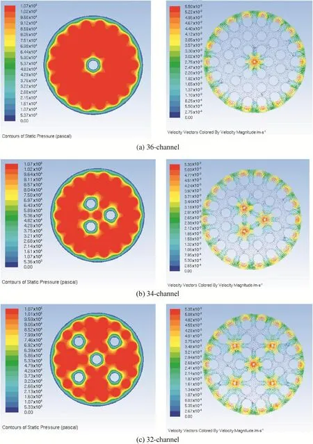
Fig.11.Distribution of pressure and permeating velocity in new membrane tubes with mean pore size of 3000 nm(z=100 mm).

Table 7 Comparison of PWF between five new membrane tubes and the original 37-channel one

Fig.11(continued).

[1]A.Pak,T.Mohammadi,S.M.Hosseinalipour,V.Allahdini,CFD modeling of porous membranes,Desalination 222(1–3)(2008)482–488.
[2]Z.X.Zhong,W.X.Li,W.H.Xing,N.P.Xu,Cross flow filtration of nanosized catalysts suspension using ceramic membranes,Sep.Purif.Technol.76(3)(2011)223–230.
[3]A.L.Ahmad,N.H.M.Yasin,C.J.C.Derek,J.K.Lim,Harvesting of microalgal biomass using MF membrane:Kinetic model,CDE model and extended DLVO theory,J.Membr.Sci.446(2013)341–349.
[4]Y.Q.Fan,H.Qi,N.P.Xu,Advance in preparation techniques of porous ceramic membranes,J.Chem.Ind.Eng.64(1)(2013)107–115(in Chinese).
[5]H.Jiang,L.Meng,R.Z.Chen,W.Q.Jin,W.H.Xing,N.P.Xu,Progress on porous ceramic membrane reactors for heterogeneous catalysis over ultra fine and nano-sized catalysts,Chin.J.Chem.Eng.21(2)(2013)205–215.
[6]P.Wu,Y.Z.Xu,Z.X.Huang,J.C.Zhang,A review of preparation techniques of porous ceramic membranes,J.Ceram.Process.Res.16(1)(2015)102–106.
[7]G.Y.Meng,Q.Dong,X.Q.Liu,D.K.Peng,Current progresses on inorganic porous separation membranes,Membr.Sci.Technol.23(4)(2003)261–268.
[8]E.E.McLeary,J.C.Jansen,F.Kapteijn,Zeolite based films,membranes and membrane reactors:Progress and prospects,Microporous Mesoporous Mater.90(1–3)(2006)198–220.
[9]Y.S.Lin,I.Kumakiri,B.N.Nair,H.Alsyouri,Microporous inorganic membranes,Sep.Purif.Methods 31(2)(2002)229–379.
[10]H.C.Yang,Y.F.Chen,C.Ye,L.S.Wan,Z.K.Xu,Advances in porous organic–inorganic composite membranes,Prog.Chem.27(8)(2015)1014–1024(in Chinese).
[11]G.Keir,V.Jegatheesan,A review of computational fluid dynamics applications in pressure-driven membrane filtration,Rev.Environ.Sci.Biotechnol.13(2)(2014)183–201.
[12]A.P.Rao,N.V.Desai,R.Rangarajan,Inorganic membranes:New materials for separation technology,J.Sci.Ind.Res.India 56(9)(1997)518–522.
[13]W.B.Peng,Optimizating ceramic membrane geometry by computational fluid dynamics(Ph.D.Thesis)Nanjing University of Technology,China,2008(inChinese).
[14]F.Springer,R.Ghidossi,E.Carretier,D.Veyret,D.Dhaler,P.Moulin,Study of the effect of geometry on wall shear stress and permeate flux for ceramic membranes:CFD and experimental approaches,Eng.Appl.Comp.Fluid 4(1)(2010)17–28.
[15]R.Ghidossi,E.Carretier,D.Veyret,D.Dhaler,P.Moulin,Optimizing the compacity of ceramic membranes,J.Membr.Sci.360(1–2)(2010)483–492.
[16]A.S.Berman,Laminar flow in channels with porous walls,J.Appl.Phys.24(9)(1953)1232–1235.
[17]R.M.Terrill,Laminar flow in a uniformly porous channel with large injection,Aeronaut.Q.16(1965)323–332.
[18]M.J.D.S.Galowin,Investigation of laminar flow in a porous pipe with variable wall suction,AIAA J.12(1974)1585–1594.
[19]S.K.Karode,Laminar flow in channels with porous walls,revisited,J.Membr.Sci.191(1–2)(2001)237–241.
[20]V.Nassehi,Modelling of combined Navier–Stokes and Darcy flows in cross flow membrane filtration,Chem.Eng.Sci.53(6)(1998)1253–1265.
[21]D.B.Das,V.Nassehi,R.J.Wakeman,A finite volume model for the hydrodynamics of combined free and porous flow in sub-surface regions,Adv.Environ.Res.7(1)(2002)35–58.
[22]K.Damak,A.Ayadi,B.Zeghmati,P.Schmitz,A new Navier–Stokes and Darcy's law combined model for fluid flow in cross flow filtration tubular membranes,Desalination 161(1)(2004)67–77.
[23]R.Ghidossi,D.Veyret,P.Moulin,Computational fluid dynamics applied to membranes:State of the art and opportunities,Chem.Eng.Process.45(6)(2006)437–454.
[24]E.Pellerin,K.Darcovich,S.Lin,C.Tam,E.Michelitsch,Turbulent transport in membrane modules by CFD simulation in two dimensions,J.Membr.Sci.100(2)(1995)139–153.
[25]Z.Cao,D.E.Wiley,A.G.Fane,CFD simulations of net-type turbulence promoters in a narrow channel,J.Membr.Sci.185(2)(2001)157–176.
[26]V.V.Ranade,A.Kumar,Fluid dynamics of spacer filled rectangular and curvilinear channels,J.Membr.Sci.271(1–2)(2006)1–15.
[27]V.V.Tarabara,M.R.Wiesner,Computational fluid dynamics modeling of the flow in a laboratory membrane filtration cell operated at low recoveries,Chem.Eng.Sci.58(1)(2003)239–246.
[28]P.Dolecek,Mathematical modeling of permeate flow in multi-channel ceramic membrane,J.Membr.Sci.100(2)(1995)111–119.
[29]P.Dolecek,J.Cakl,Permeate flow in hexagonal 19-channel inorganic membrane under filtration and back fl ush operating modes,J.Membr.Sci.149(2)(1998)171–179.
[30]Z.Yang,J.C.Cheng,C.Yang,B.Liang,Study on permeability of asymmetric ceramic membrane tubes with CFD simulation,J.Chem.Ind.Eng.66(8)(2015)3120–3129(in Chinese).
[31]W.B.Peng,H.Qi,G.L.Chen,L.L.Zou,W.H.Xing,N.P.Xu,CFD modeling of permeate process in 19-channel porous ceramic membranes,J.Chem.Ind.Eng.58(8)(2007)2021–2026(in Chinese).
 Chinese Journal of Chemical Engineering2016年10期
- Chinese Journal of Chemical Engineering的其它文章
- CFD modeling of a headbox with injecting dilution water in a central step diffusion tube☆
- Interactions between two in-line drops rising in pure glycerin☆
- Hydrodynamics of three-phase fluidization of homogeneous ternary mixture in a conical conduit—Experimental and statistical analysis
- Adsorption of Hg(II)from aqueous solution using thiourea functionalized chelating fiber☆
- Nickel(II)removal from water using silica-based hybrid adsorbents:Fabrication and adsorption kinetics☆
- Reactive dividing wall column for hydrolysis of methyl acetate:Design and control☆